
Submitted:
03 December 2025
Posted:
03 December 2025
You are already at the latest version
Abstract
This paper presents a resilient, multi-layer architecture designed to ensure reliable autonomous operation of single and multiple quadcopters. The architecture leverages the resilient spacecraft executive to hierarchically organize trajectory-planning and flight-control functions, and integrates Simplex architectures at each level to provide safety assurance. A compound subsystem expands robustness by employing multiple candidate algorithms for planning and control, while a supervisory program adapts Simplex behavior based on system states and environmental conditions to enable high-level mission management. The architecture is evaluated in simulations involving environmental uncertainties, including varying wind and obstacles, within a bridge-inspection mission using both single- and multi-quadcopter configurations. Results show that the system maintains safe and effective operation across a wide range of conditions, demonstrating scalability for cooperative multi-agent tasks.
Keywords:
quadcopters
; Simplex
; control
; planning
; inspection
; safety
; runtime assurance
; resilient architecture
1. Introduction
Multi-rotor Unmanned Aerial Vehicles (UAVs) have become a cornerstone of modern aerial robotics owing to their exceptional maneuverability, vertical take-off and landing capabilities, and reliable hovering performance [1,2]. Recent advancements in onboard sensing and edge computing have significantly enhanced the autonomy of multi-rotor UAVs, enabling them to perform complex tasks, such as environmental perception [3], trajectory planning [4], flight control [5], and mission-level management [6]. These capabilities have extended their applications beyond urban environments to include domains, such as infrastructure inspection [7,8], precision agriculture [9], and emergency response [10].
Among these applications, bridge inspection stands out as a representative and challenging task. Conventional inspection methods are often labor-intensive, time-consuming, and hazardous, typically requiring lane closures and exposing inspectors to high-risk conditions. Multi-rotor UAV-based inspection offers clear advantages in terms of safety, efficiency, and accessibility, allowing for high-resolution, multi-angle data acquisition without disrupting traffic flow [11,12]. However, the bridge inspection environment presents significant operational challenges, including wind disturbances, Global Navigation Satellite System (GNSS)-denied conditions, visual occlusion, and sensor degradation. These uncertainties impose stringent demands on UAV perception, planning, and control systems. Moreover, during long-duration missions, deviations from initial design assumptions, such as reduced sensor fidelity, computational overload, or control failures, can result in degraded performance, mission failure, or even system crashes [13,14,15]. Therefore, ensuring system-level robustness is critical for the practical deployment of UAVs in such complex environments.
Existing research has focused on improving the robustness of individual subsystems through advanced techniques, such as flight controllers [16,17,18,19,20,21,22,23,24,25,26,27,28,29] and trajectory planners [30,31,32,33]. While these methods provide localized robustness, they are typically designed under static assumptions, such as continuous sensing, bounded environmental disturbances, and sufficient onboard resources, and thus lack resilience to real-world uncertainties. Furthermore, most current UAV architectures rely on a single control pipeline with no provision for redundancy or online recovery, making them vulnerable to compounded failures.
To improve the reliability of UAVs, various approaches have been developed to enable the system to tolerate hardware or sensing failures [34]. Studies have been conducted to enable the system to detect and isolate faults in Inertial Measurement Units (IMUs) or other local sensors on UAVs [35,36,37,38], and systems have been built to adapt to actuator faults [39,40,41,42]. Research has also been conducted on mitigation methods. Poissant et al. [43] developed a ground impact and hazard mitigation method that analyzes failure modes and selects a reasonable ground impact site based on a pre-known dataset of the area when a flight fails. However, many traditional fault-tolerant methods primarily target physical component failures and typically operate reactively, intervening only after an error has been detected. This differs fundamentally from the goal of this study, which is to proactively guarantee operational safety for autonomous multi-rotor UAVs by preventing unsafe states before a failure can occur.
This work proposes a multi-layer resilient architecture for autonomous multi-rotor UAVs, specifically tailored to complex bridge inspection environments. To realize proactive safety, one leverages the Simplex architecture to enforce verifiable operational envelopes, allowing the system to preemptively intervene and avert potential hazards before safety constraints are violated. Crucially, within this framework, one incorporates a compound High-Assurance (HA) subsystem composed of multiple, diverse HA algorithm candidates to expand the system’s stable operational envelope. Consequently, this approach maximizes the utility of existing robust algorithms while enabling the safe deployment of High-Performance (HP) learning-based algorithms [44,45]. This capability is particularly significant given the growing potential of learning-based methods in advancing robotic autonomy.
To overcome the limitations of single-layer implementations and effectively handle compound environmental uncertainties, one integrates the concept of the Resilient Spacecraft Executive (RSE) [46] into our multi-layer design. This architecture establishes a hierarchical framework that explicitly coordinates decision-making across planning and control levels. Unlike isolated safety mechanisms, it ensures global system resilience through three core components: (1) a two-level Simplex subsystem deployed at both the trajectory planning and flight control layers, which unlike isolated single-layer settings, permits unified regulation based on mission requirements and system states to optimize global adaptation; (2) a runtime evaluation mechanism that dynamically selects the most appropriate HA algorithm based on system states; and (3) a mission-level monitoring module. Serving as the high-level coordination core, this module orchestrates the underlying Simplex layers to maintain an adaptive balance between performance and safety throughout the inspection mission.
This work presents a comprehensive extension of our earlier work [47]. While the prior work introduced the foundational concept of the hierarchical architecture, the present study offers a significantly expanded problem formulation, a complete description of the multi-layer decision logic, and a substantially broader set of experimental validations.
The proposed architecture has been validated in simulation within realistic bridge inspection scenarios. Leveraging pre-acquired point cloud data, the system autonomously generates coverage-aware inspection paths, performs real-time obstacle-aware trajectory planning, and manages mission execution. Its effectiveness is demonstrated not only in single-agent scenarios under wind disturbances and unknown obstacles, but also in cooperative multi-UAV missions, where the architecture is instantiated on each agent to ensure both individual safety and collective efficiency. In addition to scenario-based evaluations, an extensive Monte Carlo study has been conducted to assess robustness across a wide range of stochastic environmental uncertainties. Simulation results demonstrate that the system achieves strong operational robustness and task reliability under diverse uncertainties. Compared with existing approaches, this work provides a system-level solution that elevates robustness from individual algorithmic improvements to holistic mission assurance, verifying the effectiveness of a “multi-layer Simplex + mission monitoring” strategy for resilient UAV autonomy.
The main technical contributions of this paper are summarized as follows:
- A fault-tolerant mechanism based on a multi-level Simplex architecture, in which independent Simplex subsystems are deployed at both the trajectory planning and flight control layers, enabling robust failure detection and safe switching to HA controllers.
- A robustness-boundary extension method based on compound HA subsystems, which integrates multiple HA algorithms within each Simplex layer and uses a state-driven selection mechanism to adaptively expand the stability envelope under varying environmental and system conditions.
- A system-level adaptive coordination strategy based on a mission monitoring module, introduced as a high-level decision core that evaluates system status and environmental factors in real time, dynamically managing the behavior of the lower-level Simplex components to achieve task-level performance-safety trade-offs, which demonstrates scalability in decentralized multi-agent scenarios.
2. Related Work
This section reviews the state-of-the-art research relevant to resilient UAV autonomy. First, it examines existing approaches for robust flight control and trajectory planning under environmental uncertainties. Subsequently, it discusses the application of Simplex architectures for runtime safety assurance and the role of high-level mission coordination strategies. Finally, it identifies the limitations of current methods in handling compound failures, highlighting the necessity of the integrated multi-layer architecture proposed in this work.
2.1. Robustness in Flight Control and Trajectory Planning
Bridge inspection missions often expose UAVs to challenging environmental conditions, such as strong wind gusts, visual occlusion from complex structures, and intermittent GNSS availability. To address these issues, researchers have devoted significant effort to enhancing the robustness of both flight control and trajectory planning modules, typically under constrained and localized operating assumptions [48].
In terms of flight control, various strategies have been employed to improve disturbance rejection and ensure flight stability. Sliding Mode Control (SMC), for instance, is known for its robustness in the face of model uncertainties and external disturbances and has been widely used in turbulent wind conditions [49]. Model Predictive Control (MPC) has gained popularity due to its ability to incorporate system constraints and optimize control actions in real time [50]. In addition, adaptive control methods [51] and neural network-based compensation schemes [52] have been explored to accommodate system variations, such as changing payloads or degradation in actuator performance. More recently, hybrid approaches that combine traditional control with techniques like Extended State Observers (ESO) [53] and real-time fault detection [54] have emerged, offering improved fault tolerance and responsiveness.
On the planning side, efforts have centered around ensuring safe and effective coverage of complex structures, including arch, truss, and suspension bridges [55,56]. Algorithms capable of real-time obstacle avoidance and trajectory re-planning have been developed, often leveraging three-Dimensional (3D) point cloud data to account for structural complexity. Notable planning frameworks, such as fast-planner [32] and Euclidean signed distance field-free Gradient-based lOcal (EGO) planner [31], support high-frequency updates and dynamic obstacle avoidance in cluttered spaces, which are particularly valuable during proximity operations. Meanwhile, exploration-based methods, such as coverage planners [57,58] have been integrated with onboard perception systems to facilitate adaptive and efficient inspection path generation.
However, a common limitation among these methods is their reliance on relatively idealized conditions: uninterrupted perception, adequate onboard computing power, and predictable disturbance profiles. In actual inspection scenarios, UAVs frequently encounter abrupt occlusions, rapidly changing airflow, and unreliable positioning signals, especially when flying under decks or between bridge trusses. Under such conditions, the assumptions underlying many individual control or planning modules quickly break down. For instance, GNSS-based control loops may fail near large metallic structures, while vision systems can suffer from motion blur or low texture in over- or under-exposed areas.
To bridge this gap between algorithmic robustness and real-world reliability, researchers have begun exploring sensor fusion strategies, integrating data from vision, Light Detection And Ranging (LiDAR), barometers, and other sources to maintain state estimation even under partial failures [59,60,61,62]. Some have also turned to learning-based controllers trained in simulation to provide robust fallback behaviors in degraded or novel conditions [63]. Despite these promising directions, a key weakness remains: the lack of coordinated interaction among perception, planning, and control subsystems. When failures occur at multiple levels or when environmental conditions deteriorate rapidly, localized robustness is insufficient. The system’s vulnerability is particularly evident in low-altitude, close-structure operations, where both perception and control margins are narrow.
These observations highlight the need for a more holistic approach, one that not only improves individual subsystems but also tightly integrates them within a flexible, system-level architecture capable of dynamically adapting to uncertainty. Only through such an integrated design can UAVs maintain reliable operation throughout the highly variable conditions encountered in bridge inspection missions.
2.2. Simplex Architecture and Runtime Safety Assurance
The Simplex architecture [64] has emerged as a promising framework for enhancing safety in autonomous systems, particularly those operating in uncertain or safety-critical environments. Its core idea is to safeguard system stability by enabling a fallback from an HP controller to a formally verified HA controller when abnormal conditions are detected by the decision logic. This architecture has gained increasing traction in UAV research, where ensuring real-time safety despite unexpected disturbances is a central concern.
In UAV applications, Simplex has typically been employed at the control level to handle scenarios, such as actuator degradation [65], environmental disturbances [66], or perception failures [67]. Some recent implementations go a step further by using predictive simulation, such as look-ahead estimators or baseline simulators, to anticipate instability and trigger timely controller switching. These systems, often described as “black-box” Simplex variants, aim to retain the agility of HP controllers while maintaining the safety envelope enforced by the HA controller, all with minimal computational overhead [68].
Despite these advancements, most current applications of the Simplex framework remain limited in scope. In particular, they are often confined to a single functional domain (either flight control or path planning) and rely on static, pre-defined fallback controllers that lack adaptability [65]. Once switched, the HA controller typically remains active regardless of changes in the external environment or mission phase. This rigid design restricts the architecture’s flexibility and, more importantly, its ability to handle evolving task demands. Furthermore, decision logic is often binary and threshold-based, leading to either premature switching (wasting performance potential) or delayed response (risking system instability) [69].
Bridge inspection missions, by their nature, introduce unique operational challenges that stretch the capabilities of conventional Simplex systems. These missions are long in duration and involve transitions through drastically different flight conditions. For example, navigating beneath a bridge may require slow, highly precise movements in GNSS-denied environments, while transitioning between structural segments, might demand rapid, trajectory-wide re-planning in wind-exposed open air. Lighting conditions may vary sharply, and sensor reliability can fluctuate due to reflections or occlusions caused by the infrastructure itself. A Simplex framework that lacks dynamic reconfigurability or mission awareness will struggle to maintain both continuity and safety across such diverse operational phases.
In response to these challenges, recent research has proposed extensions to the Simplex paradigm. One such direction involves the use of compound HA subsystems, which maintain a library of robust control or planning algorithms [70]. Instead of defaulting to a single conservative fallback, the system continuously evaluates current performance, environmental conditions, and system health to select the most suitable algorithm in real time. This dynamic approach significantly expands the usable safety envelope, allowing the UAV to better balance performance and risk even during abnormal events [71]. Nevertheless, these compound approaches are still in early stages and often remain confined within individual subsystems. Without higher-level coordination or cross-layer communication, decisions made at the control level may conflict with those at the planning or mission management level [66,72]. To fully realize the potential of Simplex-based resilience, a more integrated architectural approach is needed. This approach should treat robustness not as an isolated feature but as a system-wide capability that spans multiple functional layers.
2.3. Task-Level Regulation and System-Level Coordination
Ensuring reliable and efficient UAV performance in bridge inspection missions requires more than robust local control and planning; it demands strategic regulation at the system level. This includes the ability to interpret mission objectives, monitor execution status, manage computational and sensing resources, and coordinate responses to unforeseen events. As inspection scenarios become increasingly complex and dynamic, system architectures must evolve to embed this higher level of awareness and adaptability.
One influential concept in this regard is the RSE, originally developed for autonomous spacecraft operations. RSE employs a layered control hierarchy, typically comprising deliberative, habitual, and reflexive layers [46,73]. This structure allows the system to alternate between long-term strategic planning, rule-based behavior, and rapid reflex actions depending on the urgency and nature of the situation. By incorporating risk-aware reasoning, the RSE framework enables dynamic task reconfiguration and graceful degradation in the presence of faults or environmental changes. While these ideas have shown success in space applications, their adoption in UAV systems, particularly in the context of bridge inspection, remains limited [74,75,76,77]. In such environments, UAVs operate at low altitude and near complex, often cluttered structures. Here, decision-making must account for more than just flight dynamics; it must also consider factors, such as structural geometry, inspection coverage requirements, sensor occlusions, and external disturbances, including wind gusts and lighting transitions. Relying solely on local controllers or pre-programmed behaviors is insufficient to meet these demands.
An effective task-level module for bridge inspection should fulfill several key roles. First, it must interpret the structural context, recognizing whether the UAV is navigating around trusses, piers, or under arches, and adapt planning and control parameters accordingly [78]. Second, it should track the progress of inspection tasks in real time, detecting incomplete coverage or deviations from intended paths. Third, and perhaps most critically, it should monitor the health of subsystems and environmental factors, using this information to preemptively trigger fallback actions or adjust mission priorities when needed [79]. To support this, a growing body of work has explored supervisory modules that oversee subsystem behavior and enforce task-level constraints. Some systems implement centralized health monitors or arbitration schemes that manage control delegation based on fault indicators, while others employ mission-state machines that map high-level goals to low-level behaviors. However, these approaches often lack real-time adaptability or rely on rigid logic that cannot handle compound or unexpected failure modes.
Although such architectures have demonstrated initial success in space applications, their systematic adoption in UAV-based bridge inspection, particularly in ground-level, proximity-rich environments, remains limited. In complex inspection tasks, the task-level module must be able to: (1) adapt control and planning strategies based on bridge type (e.g., truss, arch, beam); (2) monitor execution states and structural coverage in real time for dynamic task reconfiguration; and (3) respond to sensing failures, degraded flight control performance, or planning inconsistencies by triggering appropriate fallback mechanisms [75,80]. Several studies have introduced health monitoring and mission-aware arbitration modules into UAV architectures, but these are often narrowly scoped or rely on centralized, non-adaptive logic.
Therefore, it is essential to establish inter-layer communication and strategy synchronization across the mission, planning, and control layers, enabling real-time performance-safety trade-offs and adaptive operations at the system level. This coordination is especially critical in environments where external conditions, such as wind gusts, GNSS blackout zones, or visual occlusion, can change abruptly and asynchronously with mission phases. Our work addresses this coordination challenge by proposing a mission-level monitoring module that integrates closely with multi-level Simplex subsystems, enabling fault-tolerant and resilient UAV autonomy during complex bridge inspection tasks.
3. Proposed Method
To achieve integrated optimization of stability, task completion rate, and adaptability for multi-rotor UAVs (herein, quadcopters) operating in dynamic and complex environments, this study proposes a layered autonomous control architecture inspired by the RSE and the Simplex architecture. Leveraging hierarchical decision-making models from human cognitive systems, the proposed architecture decomposes the control system into three functional layers, distinguished by their hierarchical levels of decision-making and control functions: the Deliberative Layer, the Habitual Layer, and the Reflexive Layer.
3.1. Architectural Overview
As illustrated in Figure 1, one uses the decision and control hierarchy of the RSE, which is the core module of the original concept. The lower layers focus on dynamic control, while the upper layers manage trajectory planning and mission-level decision-making. The three layers are interconnected via standardized information interfaces and bidirectional data flows, forming a closed-loop control system that enhances modularity, robustness, and fault tolerance in real-time operations. Crucially, this hierarchical architecture endows individual agents with enhanced autonomy to navigate complex scenarios, thereby facilitating seamless deployment in decentralized multi-UAV missions.
The Deliberative Layer, the highest-level decision-making unit, incorporates a Mission Monitor to evaluate task feasibility and guide execution tempo by aggregating system status, energy levels, and environmental data. It orchestrates decision-making across the lower layers by managing their configuration to ensure that the selected controller-planner pair is both safe and performance-optimal.
The Habitual Layer, serving as the intermediate planning layer, is responsible for path searching and trajectory generation. It converts high-level mission sub-goals from the Deliberative Layer into executable reference trajectories that comply with UAV dynamics and environmental constraints. To ensure planning safety, this layer integrates a Simplex-based switching mechanism that reverts to a safety planner for immediate re-planning if the primary planner fails or violates constraints.
The Reflexive Layer, at the bottom of the hierarchy, executes real-time flight control tasks such as trajectory tracking. Operating at high frequencies, it generates motor-level commands based on reference trajectories and state estimates. Similar to the layer above, it features an embedded Simplex-based module to enhance fault resilience, switching to a verified safety controller in the presence of real-time disturbances.
3.2. System Metrics and Safety Constraints
The evaluation of the proposed architecture is based on two distinct categories of metrics: Mission Performance and Operational Assurance. Mission Performance metrics, such as image quality and data completeness, quantify the effectiveness of the mission outcome and are treated as objectives to be maximized. Conversely, Operational Assurance metrics, such as trajectory tracking accuracy and trajectory validity, quantify the safety and stability of the system’s operation and are enforced as inviolable constraints. The primary objective of the proposed system is to preserve mission performance while ensuring operational assurance under a wide range of system and environmental conditions.
3.2.1. Mission Performance Metrics
For inspection missions, mission performance is defined in terms of imagery quality and data completeness. In this work, one considers the UAV’s angular velocity as the dominant factor affecting imagery quality, since the rate of attitude change in the onboard camera’s Field of View (FoV) directly impacts the sharpness of the captured images [81]. A rapidly changing FoV, caused by high angular velocity, may introduce motion blur and degrade image quality [81]. To represent data completeness, one uses the coverage rate of the pre-acquired point cloud data as the primary metric. Since the system utilizes this pre-acquired data to generate the coverage plan for the inspection mission, a higher coverage rate directly indicates that the target structure has been scanned more completely.
Image Quality
It quantifies the quality of visual image data. For vision-based inspection, the severity of motion blur is linked to the ratio of the scene’s angular change rate to the sensor’s sampling rate [81]. While directly quantifying blur is complex, angular velocity serves as a high-fidelity proxy. Although transient rotational peaks can occur, they typically affect only a small fraction of the images captured during a mission. The overall quality and usability of the collected visual dataset are strongly correlated with the general stability of the flight. Therefore, one uses the mission-averaged angular velocity () as the underlying metric to reflect the general image quality. However, average deviation may mask transient large errors. To assess the worst-case performance excluding extreme outliers, one additionally employs the 95th percentile angular velocity, denoted as . This metric captures the upper bound of nominal behavior, consistent with safety assessment standards [82]. In this work, one assumes that a flight control policy with lower and would result in higher image quality.
The instantaneous angular-velocity magnitude is computed from the body-frame angular-rate components, roll rate (p), pitch rate (q), and yaw rate (r), as
The mission-averaged angular velocity over the observation period is then given by
where N denotes the total number of discrete samples collected during the mission.
Let be the instantaneous angular velocity magnitudes sorted in ascending order. The 95th percentile metric is defined as
where denotes the ceiling function.
Data Completeness
This metric evaluates mission success based on task completion and is quantified by the point cloud coverage rate (). It is defined as the ratio of the number of unique points in the scanned point cloud () to the number of points in the pre-acquired point cloud () after the inspection is completed. A trajectory planning policy with a higher indicates better data completeness. Formally,
3.2.2. Operational Assurance Metrics
Operational assurance is assessed through two primary metrics: trajectory tracking fidelity and trajectory validity. Trajectory tracking fidelity is quantified by the trajectory deviation. A higher trajectory tracking fidelity or a lower trajectory deviation directly indicates a higher degree of safety, as it confirms that the UAV is closely adhering to its safe corridor when tracking a collision-free reference trajectory through obstacles. In this work, wind is considered the main source of trajectory deviation; therefore, this metric primarily reflects the flight controller’s wind disturbance rejection capability. Trajectory validity, on the other hand, ensures that the reference trajectory itself remains safe over time. It depends on the trajectory planner’s ability to perform timely updates in response to newly detected obstacles. A failure to re-plan in a dynamic environment can render a previously valid trajectory unsafe, creating a significant mission risk even with perfect trajectory tracking fidelity.
Trajectory Tracking Fidelity
It ensures each quadcopter accurately follows the planned trajectory, which is critical for operational safety. This fidelity is quantified by the trajectory deviation, reflecting the system’s capability to reject external disturbances such as wind. The average trajectory deviation () serves as a holistic metric to evaluate the system’s performance throughout the mission. Additionally, to assess the upper bound of tracking error while mitigating the stochastic contingency of absolute peaks, one reports the 95th percentile deviation (). In this work, one assumes that a flight control policy with lower and implies higher tracking fidelity.
The instantaneous deviation is calculated as the Euclidean distance between the UAV’s actual position () and the reference position ():
The mission-averaged deviation over the duration is
and the 95th percentile metric is
Trajectory Validity
Unlike static environments, where a fixed safety margin suffices, our system operates in unknown environments in which the occupancy grid map () is incrementally updated via onboard sensors. Consequently, a previously safe trajectory may become invalid if a newly detected obstacle occludes the planned path.
To evaluate the planner’s capability to react to these environmental changes (i.e., timely re-planning), one assesses the instantaneous validity of the reference trajectory being tracked. Specifically, one checks whether the reference setpoint () at the current time step (t) overlaps with any occupied voxels in the updated map (). A valid planning policy must ensure that the reference setpoint remains in the free space () at all times. This instantaneous validity constraint is formulated as the setpoint indicator:
where denotes the occupancy status of the grid cell corresponding to the reference position .
To quantify the robustness of the flight mission, one assesses the trajectory validity rate, defined as the proportion of time steps where the reference setpoint remains in free space relative to the total number of sampling instances (N). The global validity metric is formulated as
This formulation yields a continuous score , where a value of 1 indicates a completely collision-free trajectory, while lower values quantify the extent of validity degradation due to environmental obstacles.
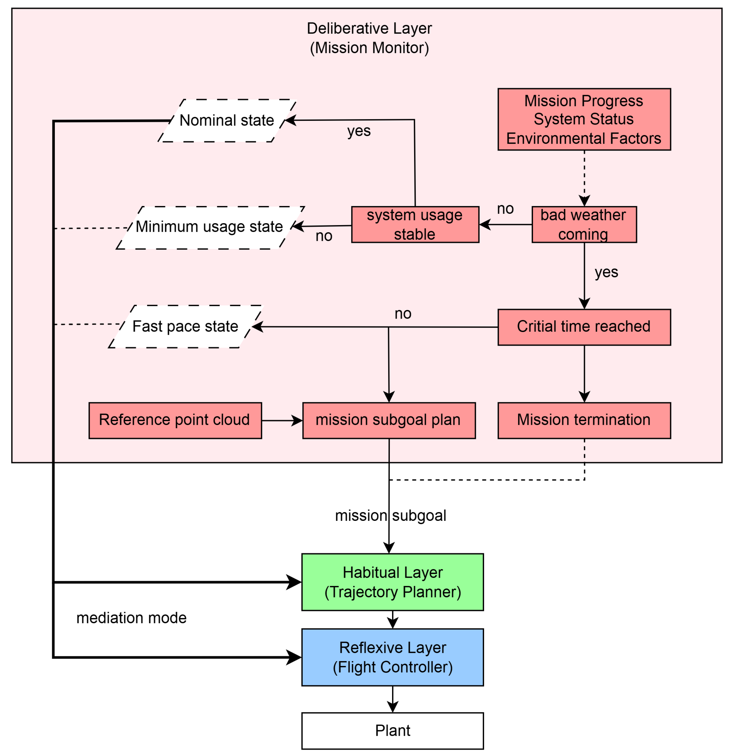
3.3. Deliberative Layer: Mission Orchestration
The Deliberative Layer functions as the “cognitive core” of the RSE architecture, enabling real-time mission adaptation, failure anticipation, and coordinated control reconfiguration. Its primary objectives are to maximize mission success rates and ensure system safety by managing inter-layer cooperation and assigning mission sub-goals according to a pre-defined mediation policy. By integrating multi-source information and modeling safety envelopes, it ensures that the UAV system maintains autonomy and resilience in uncertain, dynamic environments.
It also acts as the decision core by continuously assessing high-level system and environmental states, as depicted in Figure 2. This process involves evaluating two primary inputs: external environmental factors (e.g., deteriorating weather conditions) and internal system health (e.g., stable system usage). Based on these inputs, the monitor orchestrates the system’s overall strategy by selecting one of several operational modes for the lower layers.
This state-driven approach serves as a high-level fault-avoidance mechanism. By proactively identifying conditions that could lead to degraded performance (like resource contention indicated by unstable usage) or mission failure (like adverse weather), the Deliberative Layer preemptively adjusts the system’s behavior by assigning different mediation modes to the lower layers. For instance, the prediction of deteriorating weather triggers a re-evaluation of the mission’s urgency. If a critical time constraint has not been reached, but the mission cannot be finished at the original pace, designed to achieve reasonable data quality, the system switches to fast pace mode to accelerate task completion. Conversely, if the weather is clear but the system resource usage becomes unstable due to the computational complexity of other on-board processes, such as LiDAR-inertial odometry [83], it transitions to minimum usage mode to conserve computational resources and maintain the update rate for flight controllers and trajectory planners. Compared with reactive approaches that trigger switching only when local real-time Central Processing Unit (CPU) usage breaches a threshold, this system-level regulation enables the flight control and trajectory planning layers to preemptively prepare for resource instability, ensuring more robust and timely adaptation to adverse conditions.
While the proposed architecture incorporates a Mission Monitor Module within the deliberative layer for high-level decision-making, the primary focus of this study is to evaluate the performance and safety of implementing the Simplex architecture with the compound HA subsystem at the flight control and trajectory planning levels. Consequently, the high-level Mission Monitor is configured to assign only the nominal mediation mode and pass the coverage tour plan to the lower level. This coverage tour plan is generated using the coverage planner from [84] based on pre-acquired point-cloud data. The validation of high-level mission monitoring strategies falls outside the scope of this paper and is reserved for future work.
Figure 2.
Mission monitor at the Deliberative Layer.
3.4. Habitual Layer: Trajectory Planning
Situated between high-level task scheduling and low-level flight control, the Habitual Layer serves as a critical bridge. Its primary function is to generate dynamically feasible, obstacle-aware, and mission-efficient trajectories based on known maps and task goals. The quality of these trajectories directly influences mission success rates, flight safety, and path-tracking performance.
To enhance resilience, one integrates a Simplex architecture with a compound HA subsystem into this layer. The EXplore PLanner (EXPL) [84] is used as the HP planner due to its ability to fulfill assigned sub-goals. The compound HA subsystem is complemented by several HA planners selected for structural diversity and functional complementarity:
Each planner exhibits distinct strengths in path smoothness, robustness, or computational efficiency. Their stable operational envelopes form partially overlapping bounded regions, enabling redundant coverage and robust planner switching. This forms the trajectory-planner candidate pool of HA trajectory planning algorithms. Therefore, the Simplex architecture with a compound HA subsystem is designed as in Figure 3, where the fallback subsystem at this level is a trajectory that forces the quadrotor to perform an emergency hover.
Table 1 presents a comparison of the trajectory-planner candidates’ key features, such as obstacle-avoidance capability and CPU usage level. Subsequently, it outlines the availability of each planner within our defined mediation modes (nominal, fast pace, and minimum usage), which is determined by matching these features against the requirements of each mode.
The availability of planners, as summarized in Table 1, is adapted for the fast pace and minimum usage modes. Specifically, in fast pace mode, EXPL is deactivated due to its lower re-plan frequency, which is less suitable for real-time obstacle avoidance at high speeds. In minimum usage mode, both EXPL and EGO are disabled. The exclusion of EGO is a strategic choice, as its reliance on an iterative optimization solver is theoretically more sensitive to system-wide CPU contention, posing a risk of unpredictable performance when resources are scarce. This selective enabling of planners forms different shapes for the Simplex architecture’s decision logic at this level.
Once the set of active planners is determined, the Simplex architecture performs real-time safety monitoring to trigger a switch to the verified safety controller. The key indicators governing this switch are the planned trajectory’s clearance from obstacles and the map-update latency. To ensure that planning is based on up-to-date information, one enforces a latency threshold of 100 ms, which maintains a 10 Hz update rate for collision detection. The complete decision logic for each mode is visualized in Figure 4. For the determination of other key thresholds, please refer to the Appendix.
As shown in Figure 4, the decision trees for all modes share a similar format for safety checks. However, the planner-selection branches differ significantly. For instance, in nominal mode, the logic must choose among all four planners, whereas in minimum usage mode, the choice is simplified to only KINO or FALCO. This illustrates how the Simplex architecture achieves system-level adaptivity without altering its core safety principles. In terms of mission performance, the planners are prioritized in the order of EXPL > EGO > KINO > FALCO. Under this framework, the system prioritizes the most efficient planner available that remains within the safety envelope, given the prevailing system status and environmental factors.
From an implementation perspective, all planners are instantiated during system initialization but remain in a standby state when not active. Re-planning is triggered exclusively when a specific planner is selected. Since trajectory planning operates at a lower frequency compared to flight-control loops but demands higher computational resources, this on-demand activation strategy is adopted to optimize computational efficiency.
3.5. Reflexive Layer: Real-Time Control
As the lowest and most time-sensitive tier, the Reflexive Layer is responsible for real-time attitude regulation and trajectory tracking in disturbance-prone environments. It also integrates a Simplex architecture with a compound HA control subsystem, enabling online multi-controller execution and state-triggered dynamic switching to enhance system robustness and adaptability.
Based on a comparative analysis of wind-rejection control algorithms [16,18,19,20,21,22,23,24,25,26,27,28,29,85], Perception-Aware MPC (PAMPC) [16] was selected as the HP controller due to its smooth and robust tracking performance. The following three controllers were chosen as HA candidates based on their operational flight envelopes and compatibility with the overall system architecture:
These controllers form a candidate pool for the compound HA subsystem. The Simplex architecture at this layer is shown in Figure 5, where the fallback maneuver is an in-situ hover.
Controller selection within the Reflexive Layer is not static; it is dynamically constrained by the mediation mode set by the Deliberative Layer. This mechanism allows the UAV to adjust its behavior according to mission demands, such as prioritizing performance, safety, or computational efficiency. The availability of each controller across these modes is summarized in Table 2.
These constraints stem from safety and resource-management considerations. For example, in fast pace mode, both PAMPC and L-MPC are disabled due to their limited wind-rejection capabilities, which poses a significant risk at higher flight speeds. In minimum usage mode, the computationally intensive PAMPC is deactivated to conserve resources, ensuring the responsiveness of the core control loop and freeing CPU capacity for other critical processes.
Mode-based controller pruning is implemented through the decision logic shown in Figure 6. As illustrated in Figure 6, although the overarching decision structure is consistent across all modes, the set of available controllers changes dynamically. All modes share two core evaluations: wind speed and wind type. Wind speed is estimated using an ESO [26], while wind type is inferred from the variance of the speed estimate within a sliding window. Details on how the corresponding thresholds are selected are provided in the Appendix. The final controller selection is then pruned according to the active mode. This visualization highlights how the Reflexive Layer adapts its strategy to mission context, enforcing constraints defined by the Deliberative Layer while maintaining a consistent and verifiable decision process.
A performance hierarchy is defined as PAMPC > L-MPC > GAC > SMC. Accordingly, the system activates the highest-priority controller that satisfies stability and safety constraints given current state estimates and environmental disturbances.
At runtime, all controllers are computed at every control iteration. Because HA controllers impose a negligible computational burden and the control frequency is high, parallel execution is essential. Waiting for an HP controller to time out before executing HA controllers would introduce unsafe latency. The only exception is GAC: its adaptive network is updated only when the controller is actively engaged.
4. Experiments
A series of systematic experiments was conducted in a high-fidelity simulation environment to evaluate the proposed multi-layer resilient control architecture in complex bridge inspection tasks. Four representative scenarios were designed: (1) nominal disturbances, (2) mid-level environmental challenges, (3) high-level environmental challenges, and (4) a structural mismatch leading to mission failure. These scenarios assess the system’s robustness and evaluate key metrics for both single-UAV and multi-UAV inspection missions. Results indicate that the architecture supports reliable and resilient UAV operations under diverse uncertainties, effectively balancing performance and safety during real-time missions.
4.1. Experiment Set-Up
The mission type selected for this work is an infrastructure inspection scenario using a multi-rotor UAV. In this mission, a quadcopter equipped with an onboard RGB-D camera autonomously scans the surface of a bridge. The RGB images are used to monitor structural health, while the depth images serve both for 3D bridge model reconstruction and for collision avoidance. Because the quadcopter must fly close to the bridge to capture detailed RGB and depth data, the mission imposes strict requirements on flight performance, particularly regarding safety and data quality.
For infrastructure maintenance, such inspections are typically conducted periodically, allowing comparisons between datasets from different inspections to track structural changes over time. Accordingly, one assumes that point cloud data from previous inspections is available for coverage path planning. In our mission, this pre-existing point cloud is used as input to generate a coverage tour plan for the target bridge structure. This plan is executed through trajectory planning and the flight control level, while being dynamically updated using real-time environmental sensing data. Battery life is not considered, as most simulated inspections last under 10 minutes, well within the flight capabilities of modern UAVs.
The complete system is implemented in C++ using the Robot Operating System (ROS) framework [86], integrated with open-source simulation tools. Several open-source algorithm repositories were incorporated to accelerate development, leveraging ROS’s widespread adoption in quadrotor control and planning for computational efficiency. GAZEBO [87] is used for dynamic simulation due to its native ROS compatibility, enabling seamless publication of simulation data, such as odometry and IMU readings, as ROS topics, with dynamic model modifications supported via plugins. AirSim [88] is used for rendering onboard imagery. AirSim, an open-source simulator for UAVs and cars, is developed as a plugin for Unreal Engine 4 (UE4), providing high-fidelity visual and depth sensor feedback. UE4 also offers readily available real-world object models, making it easy to extend the simulation to additional scenarios. AirSim application programming interface allows direct programmatic access to the quadrotor’s state and onboard sensor data, which are then passed to ROS topics for further processing.
Since bridge inspection tasks are typically executed periodically to track long-term structural changes, we assume the availability of point cloud data from a previous scan, as shown in Figure 7.
4.2. Environmental Conditions
Our system uses an ESO to estimate the wind speed, and a sliding window stores the wind speed data from the last three seconds to calculate the wind variance. A wind with a variance higher than the designed threshold of 3 m/s is considered a gust; if the variance is lower than the threshold, the wind is considered sustained. The 3 m/s threshold is chosen based on closed-loop simulation evidence: GAC tracks well under sustained or low-variance wind but exhibits pronounced phase lag and weakened compensation once the 3 s variance exceeds 3 m/s; in contrast, SMC preserves bounded deviations in this regime. Hence, one uses a 3 m/s threshold as the switching boundary between GAC and SMC.
To systematically evaluate the performance and adaptability of the proposed architecture in dynamic environments, it designs a cyclical wind profile, as illustrated in Figure 8. This model is intended to simulate the complex and fluctuating wind conditions an UAV might encounter during a mission, thereby rigorously testing the system’s response mechanisms.
The wind profile consists of three repeating phases: no wind, sustained wind, and wind gust. To enhance stochasticity, the order of the sustained wind and wind gust phases differs across cycles. Scenario-specific wind-speed ranges used in our simulations are selected with reference to an industry guideline on small-UAV wind limits [89]. Furthermore, the duration of each phase is randomly selected from a uniform distribution between 30 and 90 seconds at the start of the mission.
The generation mechanism for the wind is defined as follows:
- Global Parameter Initialization: At the commencement of each simulation mission, a single random 3D unit vector is generated to define a consistent global wind direction for the entire flight. This direction remains constant for both sustained and gust phases throughout the mission.
- Sustained Wind Phase: This phase models a steady wind with minor turbulence. A base wind speed is randomly sampled between the minimum and maximum speeds for the selected speed level at the start of the mission as part of the Monte Carlo setup (detailed in Table 3). During the sustained wind phase, the actual wind speed is modeled as this base speed with a small random perturbation of ±0.5 m/s (a total range of 1 m/s) applied every 3 seconds. This creates a noisy but relatively stable wind condition.
- Wind Gust Phase: This phase simulates highly variable and unpredictable wind conditions. While the wind direction adheres to the globally defined vector, the wind speed is resampled every 3 seconds. The sampling is performed according to the mean and distribution scale parameters specified for the wind gust category in Table 3. This results in a significantly more volatile wind profile compared to the sustained wind phase.

Table 3.
Wind condition summary.
| Type | Condition | Minimum (m/s) | Maximum (m/s) |
| Sustained Wind | Low-speed | 0 | 4 |
| Mid speed | 4 | 8 | |
| High speed | 8 | 11 | |
| Very high speed | 11 | 15 | |
| Type | Condition | Mean (m/s) | Distribution scale |
| Wind Gust | Low-Variance | 4 | 1 |
| Mid variance | 5 | 4 | |
| High variance | 5 | 7 | |
| Very high variance | 5 | 11 |
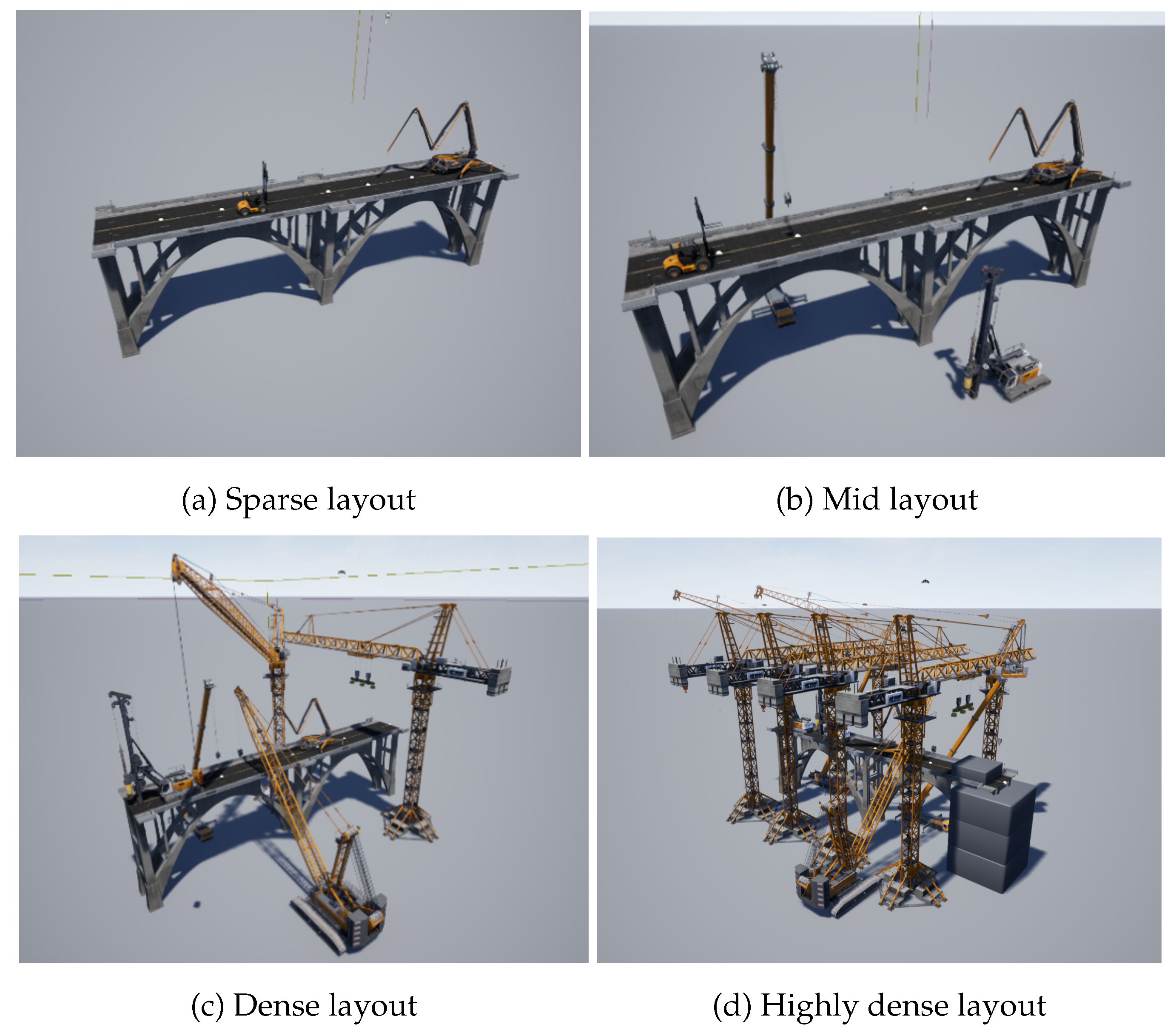
To trigger the Simplex architecture at the trajectory planning level, one places a set of construction vehicle models around the bridge model, which act as obstacles that are unknown to the system before flight. Table 4 and Figure 4 show the different levels of obstacle layout for the tests.
The sparse layout contains only two small vehicles on top of the bridge, which have a low chance of being in the way of the quadcopter during the mission. The mid layout begins to include larger vehicles on the side of the bridge, where the quadcopter often flies due to the shape of the bridge, resulting in a higher chance of having overlaps with a planned trajectory. The dense layout includes more and larger vehicles, making the environment more complex and more difficult for the HP trajectory planner. In the highly dense layout, in addition to a high concentration of construction machinery that poses a significant challenge even for the HA trajectory planners, a large portion of the bridge structure is also covered with concrete blocks. This specific obstruction is designed to cause the inspection mission to eventually stall during the flight.
Figure 9.
Simulated scene with different obstacle layouts.
To comprehensively evaluate the robustness and adaptability of the proposed multi-layer resilient architecture, a series of simulation experiments was conducted under four progressively challenging operational environments: nominal, off-nominal, edge, and malformed. These scenarios represent increasing levels of environmental disturbance and structural uncertainty, ranging from mild environmental conditions to severely compromised layouts that impede mission completion. All test cases were initialized with identical mission goals, which are to inspect the surface of the target bridge using pre-acquired point cloud data, allowing for direct and controlled comparisons of system performance and adaptive behavior:
- Nominal Case: Introduces low-speed sustained wind, low-variance wind gusts, and a sparse obstacle layout. The objective is to assess the system’s capacity to tolerate mild disturbances, where the system is expected to implement the HP algorithms most of the time while minimizing performance degradation.
- Off-nominal Case: Simulates mid-level sustained wind, low-variance wind gusts, and a mid layout. This environment is designed to trigger adaptive switching from HP to HA modules (e.g., GAC, SMC, EGO), demonstrating the trade-off between performance and safety when necessary.
- Edge Case: Emulates high-speed sustained wind, high-variance wind gusts, and a dense layout. It is intended to test the full operational boundaries of the system and its ability to maintain safety.
- Malformed Case: Imposes very high-speed sustained wind, very high-variance wind gusts, and a highly dense layout, resulting in partial mission infeasibility due to unreachable portions of the structure. The goal is to evaluate how the system handles mission failure, specifically whether it can degrade gracefully without violating safety constraints. In the current implementation, the system persists in its scanning attempts but is configured to terminate the mission if the inspection coverage fails to increase over a two-minute window. Note that in practical deployment, this behavior could be adapted to execute alternative strategies, such as exploring the surrounding space or loitering to await human intervention.
To isolate the performance of the safety switching logic, the system is assumed to operate under nominal environmental and system conditions throughout the simulations, and the mission monitor module at the Deliberative Layer outputs only the nominal mediation mode.
4.3. Testing Results
It evaluates three testable claims that characterize how the proposed system compares to the baseline across the aforementioned four environments:
- Performance fidelity - to verify that, under feasible conditions, the proposed approach preserves mission effectiveness at the level of the baseline, as reflected in comparable coverage, , and within the baseline’s error bounds.
- Safety gains - to assess whether, under adverse conditions, the proposed approach provides stronger operational assurance than the baseline, maintaining while reducing and .
- Controlled degradation - to confirm that, when HA switching is triggered, the proposed approach exhibits deliberate, safety-preserving degradation: and may rise modestly but remain reasonable, and coverage is essentially preserved.
Here, the baseline denotes the highest-performance single-stack without the Simplex safety architecture: HP planner (EXPL) and controller (PAMPC) only, with no runtime switching to HA subsystems.
To assess performance and robustness, 100 Monte Carlo simulations were conducted per scenario. The statistical results for mission performance and operational assurance are summarized in Table 5 and Table 6. Bar-plot comparisons of baseline versus proposed across all scenarios are shown in Figure 10 (mission performance) and Figure 11 (operational assurance). In both figures, horizontal dashed lines denote the image-blur threshold deg/s and the deviation envelope m (see Appendix ).
In the nominal scenario, the proposed system’s performance is comparable to that of the baseline: coverage (96.25% vs. 95.82%) and average angular velocity (26.66 vs. 26.53 deg/s) fall within a similar statistical range under nominal wind conditions and sparse obstacles. Safety remains unaffected: , and and are comparable. Mechanism: the Reflexive Layer operates on the HP controller, and the Habitual Layer uses the HP planner by default; HA is only occasionally triggered, resulting in no noticeable performance penalty.
In the off-nominal scenario, performance remains comparable to the baseline (coverage: 95.64% vs. 95.53%; : 28.89 vs. 26.03 deg/s) under mid-level wind and mid layout. Critically, safety improves substantially: decreases from 0.099 m to 0.043 m () and from 0.226 m to 0.115 m (), while . Mechanism: wind-speed/type checks trigger HA controllers (GAC/SMC) when needed.
In the edge scenario, coverage remains 95.12% with a small increase in to 31.98 deg/s under high wind and dense obstacles. Safety gains are pronounced versus baseline: rises from 98.70% to 99.97% (≈43× fewer violations), drops from 0.130 m to 0.044 m (), and from 0.236 m to 0.123 m (). The flight data comparison for the edge scenario is presented as a representative case study, as the frequent activation and switching of the HA controllers in this environment best illustrate the dynamic behavior of the Simplex architecture during mission execution. In Figure 12(a), under wind disturbances baseline frequently exceeds the deviation safety threshold, exhibiting sustained oscillations and repeated crossings due to the HP controller’s limited wind-rejection capability. In contrast, the proposed system shows only short spikes that quickly damp out and then remain within . In Figure 12(b), the proposed system exhibits slightly higher angular velocity than the baseline under wind. This is expected: when SMC is engaged, the controller executes more aggressive maneuvers to eliminate the trajectory deviation, leading to a modest increase in while preserving safety. Together, they directly substantiate the cross-scenario trends: safety metrics improve markedly with the proposed system, and the slight increase in is an intentional trade-off for robust envelope protection.
In the malformed scenario, the environment contains extensive occlusions and structurally unreachable regions; therefore, full coverage is physically unattainable regardless of control performance. Under the same high-wind and high-density obstacle conditions, the proposed system achieves 63.53% coverage over the reachable portion while preserving safety: , m). Compared with the baseline, and are reduced by ∼78.2% (0.236→0.0515 m) and ∼69.7% (0.472→0.143 m), respectively, preventing divergence beyond . Mechanism: when HP pipelines face persistent constraint violations, both layers revert to HA, and the mission terminates if coverage plateaus for two minutes, prioritizing safety over completeness.
To complement Table 5 and Table 6, Figure 13 visualizes the detailed data distribution across 100 experimental runs. While most data points cluster tightly around the mean, the box plots reveal a small number of outliers that exceed the safety threshold. Additionally, Figure 14 illustrates the UAV’s execution trajectories, showing that it consistently maintains the required stand-off distance from the bridge structure across all scenarios. This spatial consistency demonstrates that the proposed system can reliably accomplish the mission tasks under diverse environmental conditions.
Overall, the proposed architecture (i) preserves performance where feasible, (ii) delivers substantial safety gains in adverse conditions, and (iii) trades a small increase in for envelope protection and near-100% trajectory validity. The bar plots in Figure 10Figure 11 make these trends explicit; dashed lines indicate the thresholds derived in the Appendix.
Figure 13.
Data distributions.
Figure 14.
Executed trajectories.
4.4. Multi-UAV Operating Case
To demonstrate the scalability and collaborative efficiency of the proposed resilient architecture, the bridge inspection mission was executed using a decentralized fleet of three quadcopters. In this setup, the global inspection task was partitioned into sub-regions, and each agent independently ran the full stack of the proposed multi-layer architecture. This ensures that safety guarantees are enforced locally on each agent, regardless of the behavior of the others. A direct comparison with the baseline system is omitted in this multi-UAV scenario because the baseline HP planner lacks intrinsic deconfliction capabilities, making it unable to perform the necessary trajectory re-planning and avoidance with respect to other UAVs’ reference trajectories during simultaneous flight.
The results are presented in Table 7 and Table 8. A comparison with single-agent results reveals a dramatic improvement in mission efficiency. The total mission time in the nominal scenario is reduced to 95.81 seconds, representing a substantial efficiency gain compared to the single-agent execution. This improvement is primarily due to the spatial decomposition of the mission: each UAV is assigned a localized sector, eliminating the extensive transit times and circuitous flight paths inherent to single-agent operations.
Despite the increased density of aerial traffic, the safety metrics remain consistent with the single-agent baseline. As detailed in Table 8, trajectory validity remains above 99.9% across the nominal, off-nominal, and edge scenarios, and the average trajectory deviation is maintained below 0.06 m even in the Edge case. The angular velocity metrics in Table 7 show a slight increase in the edge scenario (mean 33.94 deg/s) compared to the nominal case (26.80 deg/s), reflecting the active compensation required for high-speed wind gusts. However, the low standard deviation indicates that the decentralized Simplex architecture effectively suppresses disturbances and prevents unsafe oscillations.
Even under these “mission-impossible” conditions, the multi-agent team demonstrated graceful degradation. The system achieved a coverage rate of 76.49%, notably higher than the single-agent result (63.53%) in the same environment. This improvement is primarily driven by the parallel execution capability of the multi-agent system. Unlike the single-agent scenario, where the mission stalls when the UAV encounters an occlusion, the multi-UAV configuration allows other agents to continue scanning unobstructed sections of the structure. Importantly, the safety constraints were never compromised; with a trajectory validity of 99.41% and an average deviation of only 0.066 m.
The comparative trends across scenarios are visually summarized in Figure 15 and Figure 16. Consistent with the single-agent behavioral patterns observed in Figure 10 and Figure 11, these metrics show that although environmental severity affects mission-performance efficiency (Figure 15), operational assurance remains strictly enforced (Figure 16).
It is worth noting that the data distribution in the multi-UAV case (Figure 17) exhibits an even tighter interquartile range compared to the single-agent baseline. This increased determinism can be attributed to the significantly reduced mission duration inherent in multi-agent cooperation. Because the fleet completes the scanning task more quickly, the agents are exposed to the stochastic wind field for a shorter period. This reduction in “environmental exposure time” limits the accumulation of integral errors and random disturbances, indicating that multi-UAV deployment offers a dual benefit: it not only accelerates task completion but also enhances the overall predictability of system performance under uncertainty.
Figure 15.
Comparison of mission performance metrics (multi-UAV).
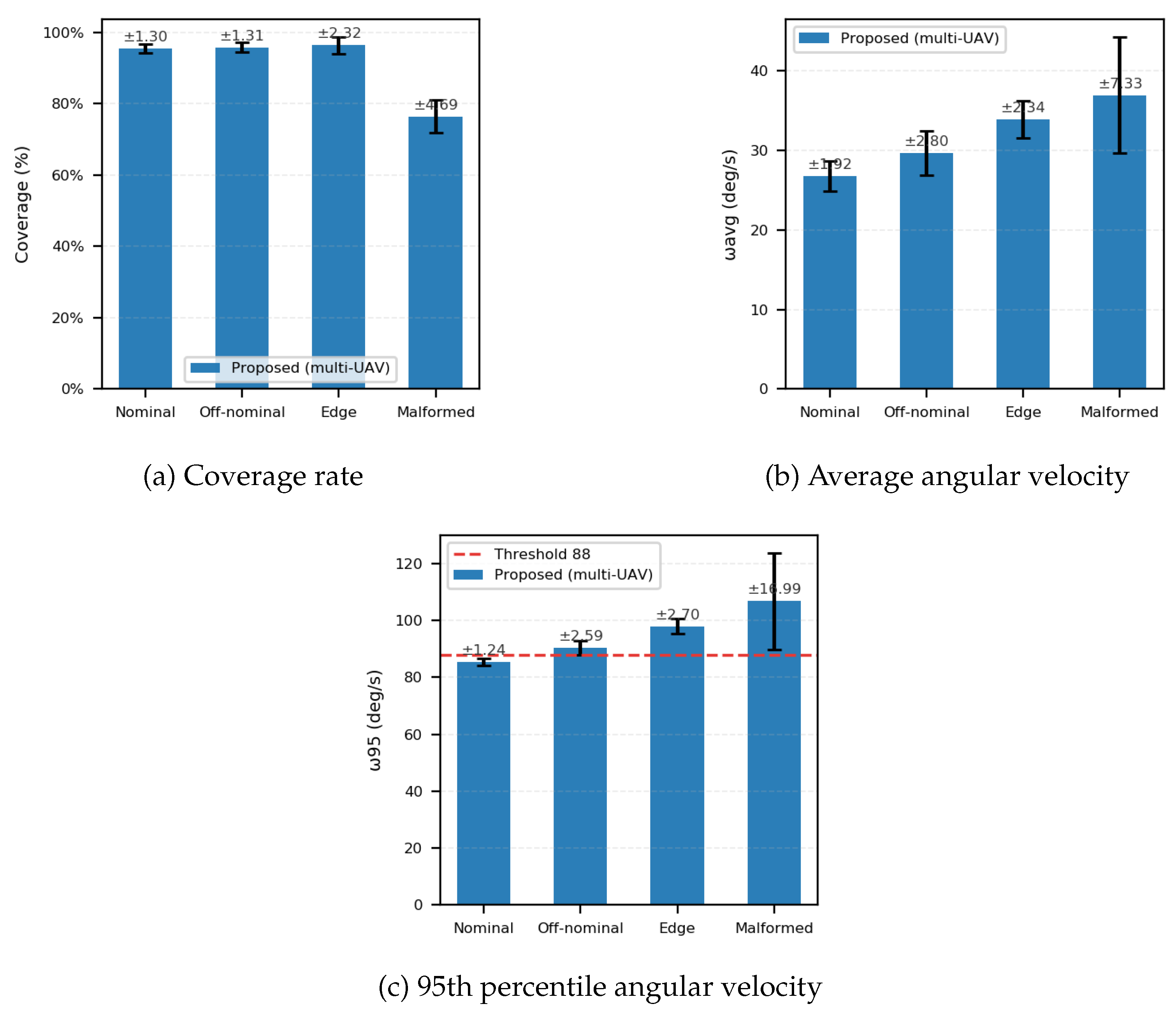
Figure 16.
Comparison of operational assurance metrics (multi-UAV).
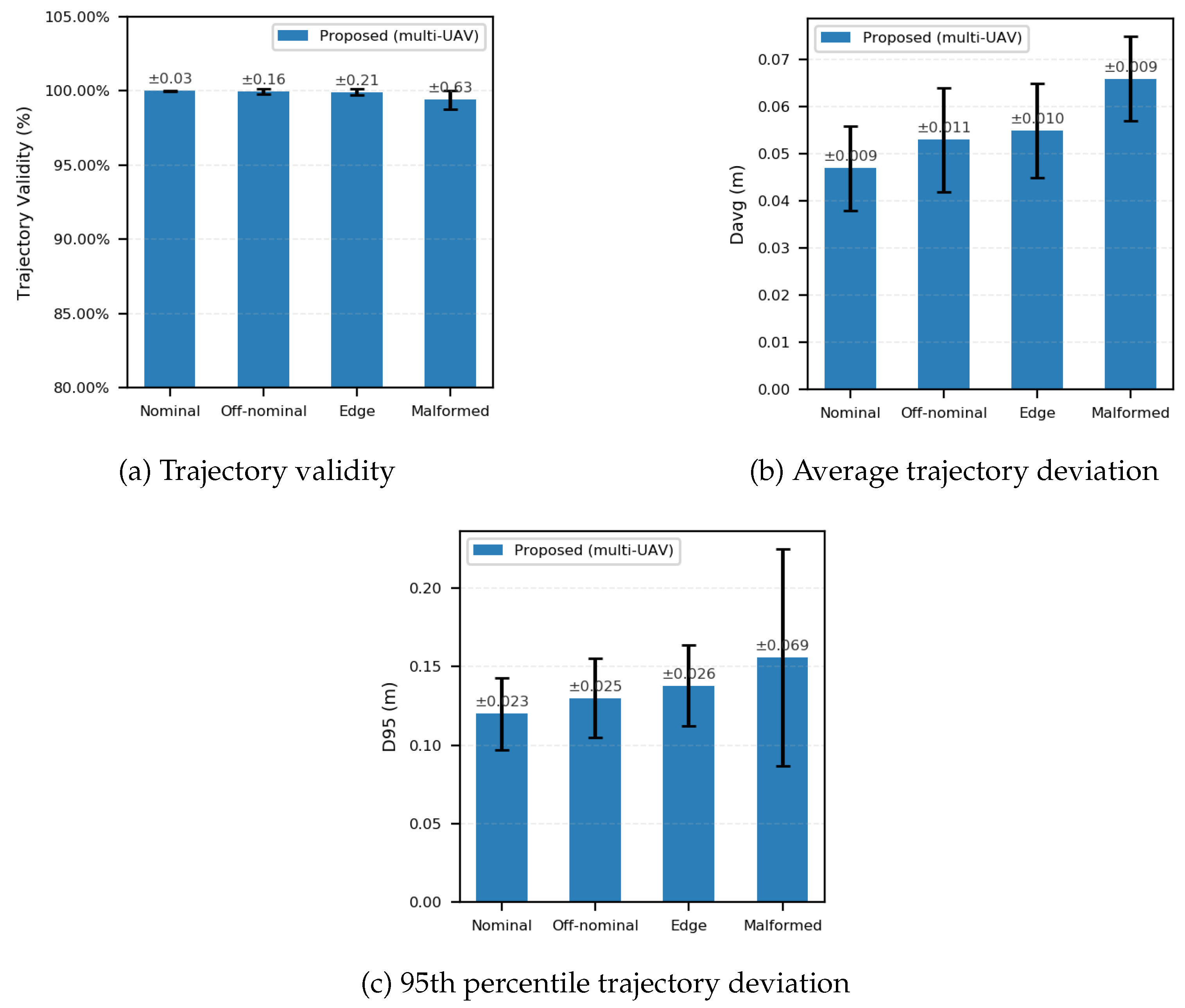
Figure 17.
Data distribution (multi-UAV).
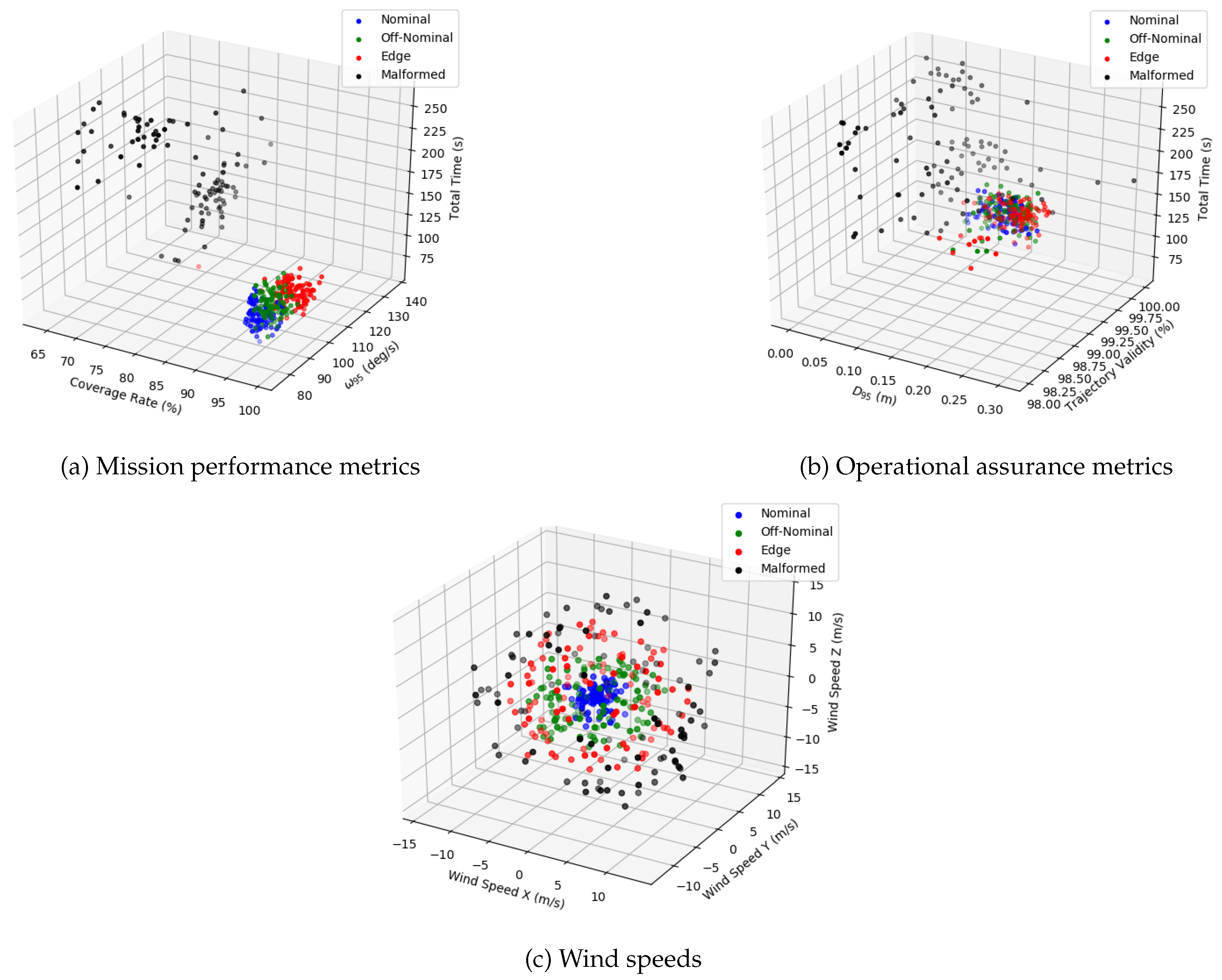
Figure 18 depicts the resulting trajectories from a multi-UAV mission. The traces show clear spatial deconfliction, with agents adhering to their assigned inspection corridors while dynamically avoiding obstacles and compensating for wind disturbances, validating the efficacy of the distributed planning and control layers.
5. Conclusion
This paper presents a multi-layer (Deliberative–Habitual–Reflexive) resilience architecture designed for uncertain environments. By embedding the Simplex framework simultaneously in the trajectory-planning and flight-control layers and introducing a High-Assurance (HA) subsystem, the proposed approach maintains mission performance and operational assurance in a bridge inspection task. System-level evaluation using high-fidelity simulations and 100-run Monte Carlo statistics demonstrates that the architecture preserves performance fidelity under feasible conditions, with coverage, average angular velocity, and 95th percentile angular velocity remaining within or near the baseline statistical range in nominal and off-nominal scenarios. Under strongly perturbed and cluttered environments, such as edge and malformed cases, the system achieves substantial safety improvements, reducing trajectory deviations by 50–70% while maintaining near-perfect trajectory validity, thereby preventing sustained boundary violations or divergence. When HA subsystems are activated, the architecture trades a modest increase in angular velocity for stable deviation convergence, preserving mission availability and data quality while strictly enforcing safety constraints. The approach also scales effectively to multi-UAV coordination: in a three-vehicle distributed instance, each vehicle executes the full stack locally, sustaining operational assurance while significantly reducing total mission time, and demonstrating team-level graceful degradation under malformed conditions by achieving higher attainable coverage without compromising safety. Overall, the proposed multi-layer resilient system elevates robustness from the level of individual algorithms to the system architecture, ensuring consistent performance under nominal conditions, enhanced safety under adverse conditions, and reliable operation across both single- and multi-agent missions. Future work will focus on implementing and validating mediation strategies in the high-level mission monitor module and incorporating systematic significance testing and ablation studies to further quantify the contributions of each architectural component.
Appendix A
This appendix provides details on the derivation and selection of the operational thresholds used in our experiments. The thresholds are grounded in physical constraints, empirical data, and safety considerations, ensuring that mission performance and operational assurance remain within acceptable bounds.
Tracking and Obstacle Safety Deviations
The selection of operational thresholds is grounded in the UAV’s physical characteristics and empirical performance data. The trajectory deviation and obstacle safety thresholds are intrinsically linked. Existing literature shows that UAVs used for bridge inspection typically range from compact models, such as the DJI Phantom series (35 cm wheelbase), to mid-sized industrial platforms like the Matrice series (65 cm wheelbase) [90]. Our custom-built platform, with a 40 cm wheelbase, falls squarely within this standard operational range, offering a trade-off between the portability of consumer drones and the payload capacity of larger industrial frames. A conservative safety principle is established by defining the UAV’s effective radius, which is 20 cm, half of its wheelbase. The maximum allowable tracking deviation is set to . A deviation exceeding this value signifies that the UAV’s center has moved beyond its physical footprint from the reference path, indicating a significant control failure. Correspondingly, the minimum obstacle safety clearance for the planner is defined as the sum of the UAV’s radius and the maximum permissible deviation as . This ensures that even under worst-case (but still acceptable) tracking performance, a safety buffer equivalent to the UAV’s radius is maintained between the vehicle’s edge and any obstacle. This principle provides a scalable and physically grounded safety margin.
Wind Speed Threshold
The wind speed threshold of 3 m/s was determined empirically through repeated simulations in a Gazebo environment utilizing a physics-based wind plugin. This value represents the critical point for sustained wind conditions, where the HP controller (PAMPC [16]) consistently began to violate the cm tracking constraint. It therefore serves as a data-driven, preemptive trigger to switch to a more robust controller (e.g., SMC [27] or GAC [28], which are designed for higher disturbances), before the primary safety constraint is breached.
Angular Velocity Threshold
One derives the critical angular velocity () that induces a one-pixel motion blur for our specific hardware (Intel RealSense D435) under bright, outdoor lighting.
The relevant camera and environmental parameters are:
- : Sensor width ( mm for the D435’s 1/4" sensor, yielding a 3.0 µm pixel pitch).
- : Image width in pixels (1280 pixels).
- : Camera focal length ( mm for the D435).
- : Exposure time (1.0 ms or s for bright conditions).
- : Motion blur threshold (1 pixel).
The derivation proceeds as follows:
- Pixel Size Calculation: The physical size of a single pixel () is:
- Permissible Blur Distance: The maximum blur distance on the sensor is
- Maximum Linear Velocity on Sensor: The corresponding velocity () is
- Critical Angular Velocity: Using the pinhole camera approximation (), one solves for :
This derivation provides a physical upper bound of . To ensure a conservative safety margin, one adopts a practical threshold such that angular velocities exceeding are considered to induce significant motion blur.
CPU Utilization Threshold
To ensure real-time performance, the CPU utilization threshold is set at 80%. This decision is grounded in established real-time systems theory, which states that even under ideal conditions, schedulability cannot be guaranteed at full CPU utilization [91]. For non-hard real-time operating systems like the Linux-based distribution on our target platform (NVIDIA Jetson Xavier), this consideration is even more critical. Empirical studies have demonstrated that as CPU load approaches saturation on such systems, task scheduling latencies can increase non-linearly, jeopardizing the determinism of the control loop [92]. Furthermore, managing computational resources to maintain the stability of critical processes is a well-documented challenge in deploying complex autonomous systems on embedded platforms like UAVs [93]. Consequently, reserving a 20% headroom is a deliberate engineering choice to accommodate these non-deterministic effects—such as OS scheduling latencies, daemon process interference, and transient load spikes—thereby ensuring the stability and predictability of the flight control loop.
Additional factors, such as computational latency in the flight controller or trajectory planner and delayed map updates, are managed via conservative thresholds within the logic flow. These measures prevent unsafe behavior, such as planning based on outdated environmental data or insufficient inter-UAV trajectory separation in multi-agent missions, although they are not employed as formal metrics for operational assurance in this formulation.
Author Contributions
Conceptualization, Z.S. and D.K.; methodology, Z.S. and D.K.; software, Z.S.; validation, Z.S. and D.K.; formal analysis, Z.S. and D.K.; investigation, Z.S. and D.K.; resources, D.K.; data curation, Z.S.; writing—original draft preparation, Z.S. and D.K.; writing—review and editing, Z.S. and D.K.; visualization, Z.S.; supervision, D.K.; project administration, D.K. All authors have read and agreed to the published version of the manuscript.
Funding
This research received no external funding.
Data Availability Statement
Data sharing is not applicable to this article.
Conflicts of Interest
The authors declare no conflicts of interest.
References
- Mohsan, S.A.H.; Othman, N.Q.H.; Li, Y.; Alsharif, M.H.; Khan, M.A. Unmanned aerial vehicles (UAVs): Practical aspects, applications, open challenges, security issues, and future trends. Intelligent service robotics 2023, 16, 109–137. [CrossRef]
- Altawy, R.; Youssef, A.M. Security, privacy, and safety aspects of civilian drones: A survey. ACM Transactions on Cyber-Physical Systems 2016, 1, 1–25. [CrossRef]
- Liang, H.; Lee, S.C.; Bae, W.; Kim, J.; Seo, S. Towards UAVs in construction: advancements, challenges, and future directions for monitoring and inspection. Drones 2023, 7, 202. [CrossRef]
- Yang, Y.; Leeghim, H.; Kim, D. Dubins Path-Oriented Rapidly Exploring Random Tree* for Three-Dimensional Path Planning of Unmanned Aerial Vehicles. Electronics 2022, 11. [CrossRef]
- Lee, K.; Choi, D.; Kim, D. Incorporation of Potential Fields and Motion Primitives for the Collision Avoidance of Unmanned Aircraft. Applied Sciences 2021, 11. [CrossRef]
- Pasha, J.; Elmi, Z.; Purkayastha, S.; Fathollahi-Fard, A.M.; Ge, Y.E.; Lau, Y.Y.; Dulebenets, M.A. The drone scheduling problem: A systematic state-of-the-art review. IEEE Transactions on Intelligent Transportation Systems 2022, 23, 14224–14247. [CrossRef]
- Aela, P.; Chi, H.L.; Fares, A.; Zayed, T.; Kim, M. UAV-based studies in railway infrastructure monitoring. Automation in Construction 2024, 167, 105714. [CrossRef]
- Choi, D.; Bell, W.; Kim, D.; Kim, J. UAV-Driven Structural Crack Detection and Location Determination Using Convolutional Neural Networks. Sensors 2021, 21, 2650. [CrossRef]
- Kok, Z.H.; Shariff, A.R.M.; Alfatni, M.S.M.; Khairunniza-Bejo, S. Support vector machine in precision agriculture: A review. Computers and Electronics in Agriculture 2021, 191, 106546. [CrossRef]
- Wan, Y.; Zhong, Y.; Ma, A.; Zhang, L. An accurate UAV 3-D path planning method for disaster emergency response based on an improved multiobjective swarm intelligence algorithm. IEEE Transactions on Cybernetics 2022, 53, 2658–2671. [CrossRef]
- Abdallah, A.M.; Atadero, R.A.; Ozbek, M.E. A state-of-the-art review of bridge inspection planning: Current situation and future needs. Journal of Bridge Engineering 2022, 27, 03121001. [CrossRef]
- Wang, F.; Zou, Y.; Chen, X.; Zhang, C.; Hou, L.; del Rey Castillo, E.; Lim, J.B. Rapid in-flight image quality check for UAV-enabled bridge inspection. ISPRS Journal of Photogrammetry and Remote Sensing 2024, 212, 230–250. [CrossRef]
- Ameli, Z.; Aremanda, Y.; Friess, W.A.; Landis, E.N. Impact of UAV hardware options on bridge inspection mission capabilities. Drones 2022, 6, 64. [CrossRef]
- Jeong, E.; Seo, J.; Wacker, J.P. UAV-aided bridge inspection protocol through machine learning with improved visibility images. Expert Systems with Applications 2022, 197, 116791. [CrossRef]
- Tang, Z.; Peng, Y.; Li, J.; Li, Z. UAV 3D Modeling and Application Based on Railroad Bridge Inspection. Buildings 2023, 14, 26. [CrossRef]
- Falanga, D.; Foehn, P.; Lu, P.; Scaramuzza, D. PAMPC: Perception-aware model predictive control for quadrotors. In Proceedings of the 2018 IEEE/RSJ International Conference on Intelligent Robots and Systems (IROS). IEEE, 2018, pp. 1–8.
- Rauniyar, S.; Bhalla, S.; Choi, D.; Kim, D. EKF-SLAM for Quadcopter Using Differential Flatness-Based LQR Control. Electronics 2023, 12, 1113. [CrossRef]
- Zhang, C.; Zhou, X.; Zhao, H.; Dai, A.; Zhou, H. Three-dimensional fuzzy control of mini quadrotor UAV trajectory tracking under impact of wind disturbance. In Proceedings of the 2016 International Conference on Advanced Mechatronic Systems (ICAMechS). IEEE, 2016, pp. 372–377.
- Aboudonia, A.; El-Badawy, A.; Rashad, R. Disturbance observer-based feedback linearization control of an unmanned quadrotor helicopter. Proceedings of the Institution of Mechanical Engineers, Part I: Journal of Systems and Control Engineering 2016, 230, 877–891. [CrossRef]
- Wang, C.; Song, B.; Huang, P.; Tang, C. Trajectory tracking control for quadrotor robot subject to payload variation and wind gust disturbance. Journal of Intelligent & Robotic Systems 2016, 83, 315–333. [CrossRef]
- Chen, Y.m.; He, Y.l.; Zhou, M.F. Decentralized PID neural network control for a quadrotor helicopter subjected to wind disturbance. Journal of Central South University 2015, 22, 168–179. [CrossRef]
- Tran, N.K.; Bulka, E.; Nahon, M. Quadrotor control in a wind field. In Proceedings of the 2015 International Conference on Unmanned Aircraft Systems (ICUAS). IEEE, 2015, pp. 320–328.
- Chen, Y.; He, Y.; Zhou, M. Modeling and control of a quadrotor helicopter system under impact of wind field. Research Journal of Applied Sciences, Engineering and Technology 2013, 6, 3214–3221. [CrossRef]
- Alexis, K.; Nikolakopoulos, G.; Tzes, A. Switching model predictive attitude control for a quadrotor helicopter subject to atmospheric disturbances. Control Engineering Practice 2011, 19, 1195–1207. [CrossRef]
- Munoz, L.E.; Castillo, P.; Sanahuja, G.; Santos, O. Embedded robust nonlinear control for a four-rotor rotorcraft: Validation in real-time with wind disturbances. In Proceedings of the 2011 IEEE/RSJ International Conference on Intelligent Robots and Systems. IEEE, 2011, pp. 2682–2687.
- Lv, T.; Yang, Y.; Chai, L. Extended state observer based MPC for a quadrotor helicopter subject to wind disturbances. In Proceedings of the 2019 Chinese Control Conference (CCC). IEEE, 2019, pp. 8206–8211.
- Besnard, L.; Shtessel, Y.B.; Landrum, B. Quadrotor vehicle control via sliding mode controller driven by sliding mode disturbance observer. Journal of the Franklin Institute 2012, 349, 658–684. [CrossRef]
- Bisheban, M.; Lee, T. Geometric adaptive control with neural networks for a quadrotor in wind fields. IEEE Transactions on Control Systems Technology 2020, 29, 1533–1548. [CrossRef]
- Yao, D.; Xu, J.; Tang, Y. Extended-State Observer-Based Integral Sliding-Mode Control for a Quadrotor. In Proceedings of the 2018 37th Chinese Control Conference (CCC), Wuhan, China, 2018; pp. 3078–3083.
- Shu, J.; Xia, Z.; Gao, Y. BIM-Based Trajectory Planning for Unmanned Aerial Vehicle-Enabled Box Girder Bridge Inspection. Remote Sensing 2025, 17. [CrossRef]
- Zhou, X.; Wang, Z.; Ye, H.; Xu, C.; Gao, F. Ego-planner: An esdf-free gradient-based local planner for quadrotors. IEEE Robotics and Automation Letters 2020, 6, 478–485. [CrossRef]
- Zhou, B.; Gao, F.; Wang, L.; Liu, C.; Shen, S. Robust and efficient quadrotor trajectory generation for fast autonomous flight. IEEE Robotics and Automation Letters 2019, 4, 3529–3536. [CrossRef]
- Zhang, J.; Hu, C.; Chadha, R.G.; Singh, S. Falco: Fast likelihood-based collision avoidance with extension to human-guided navigation. Journal of Field Robotics 2020, 37, 1300–1313. [CrossRef]
- Shraim, H.; Awada, A.; Youness, R. A survey on quadrotors: Configurations, modeling and identification, control, collision avoidance, fault diagnosis and tolerant control. IEEE Aerospace and Electronic Systems Magazine 2018, 33, 14–33. [CrossRef]
- Nguyen, H.; Berbra, C.; Lesecq, S.; Gentil, S.; Barraud, A.; Godin, C. Diagnosis of an inertial measurement unit based on set membership estimation. In Proceedings of the 2009 17th mediterranean conference on control and automation. IEEE, 2009, pp. 211–216.
- Rafaralahy, H.; Richard, E.; Boutayeb, M.; Zasadzinski, M. Simultaneous observer based sensor diagnosis and speed estimation of unmanned aerial vehicle. In Proceedings of the 2008 47th IEEE Conference on Decision and Control. IEEE, 2008, pp. 2938–2943.
- Berbra, C.; Lesecq, S.; Martinez, J. A multi-observer switching strategy for fault-tolerant control of a quadrotor helicopter. In Proceedings of the 2008 16th Mediterranean Conference on Control and Automation. IEEE, 2008, pp. 1094–1099.
- Freddi, A.; Longhi, S.; Monteriu, A. A model-based fault diagnosis system for a mini-quadrotor. In Proceedings of the 7th workshop on Advanced Control and Diagnosis, 2009, pp. 19–20.
- Guo, Y.; Jiang, B.; Zhang, Y. A novel robust attitude control for quadrotor aircraft subject to actuator faults and wind gusts. IEEE/CAA Journal of Automatica sinica 2017, 5, 292–300. [CrossRef]
- Jain, T.; Yamé, J.J.; Sauter, D. Model-free reconfiguration mechanism for fault tolerance. International Journal of Applied Mathematics and Computer Science 2012, 22, 125–137. [CrossRef]
- Jamouli, H.; El Hail, M.A.; Sauter, D. A mixed active and passive GLR test for a fault tolerant control system. International Journal of Applied Mathematics and Computer Science 2012. [CrossRef]
- Patton, R.J.; Kambhampati, C.; Casavola, A.; Zhang, P.; Ding, S.; Sauter, D. A generic strategy for fault-tolerance in control systems distributed over a network. European journal of control 2007, 13, 280–296. [CrossRef]
- Poissant, A.; Castano, L.; Xu, H. Ground impact and hazard mitigation for safer uav flight response. In Proceedings of the 2018 International Conference on Unmanned Aircraft Systems (ICUAS). IEEE, 2018, pp. 1075–1084.
- Wu, H.; Wang, W.; Wang, T.; Suzuki, S. Model-free uav navigation in unknown complex environments using vision-based reinforcement learning. Drones 2025, 9, 566. [CrossRef]
- Romero, A.; Song, Y.; Scaramuzza, D. Actor-critic model predictive control. In Proceedings of the 2024 IEEE International Conference on Robotics and Automation (ICRA). IEEE, 2024, pp. 14777–14784.
- McGhan, C.L.; Vaquero, T.; Subrahmanya, A.R.; Arslan, O.; Murray, R.; Ingham, M.D.; Ono, M.; Estlin, T.; Williams, B.; Elaasar, M. The resilient spacecraft executive: An architecture for risk-aware operations in uncertain environments. In Aiaa Space 2016; AIAA, 2016; p. 5541.
- Shi, Z.; Kim, D. Adaptive Resilient Architecture for Autonomous Quadrotor Operations under Uncertainty. In Proceedings of the 2025 10th Asia-Pacific Conference on Intelligent Robot Systems (ACIRS), 2025. Accepted for publication.
- KIM, D. Efficient Navigation for Unmanned Agents in Sparse Wireless Sensor Networks. TRANSACTIONS OF THE JAPAN SOCIETY FOR AERONAUTICAL AND SPACE SCIENCES 2021, 64, 283–287. [CrossRef]
- Young, K.D.; Utkin, V.I.; Ozguner, U. A control engineer’s guide to sliding mode control. IEEE transactions on control systems technology 1999, 7, 328–342. [CrossRef]
- Holkar, K.; Waghmare, L.M. An overview of model predictive control. International Journal of control and automation 2010, 3, 47–63.
- Mo, H.; Farid, G. Nonlinear and adaptive intelligent control techniques for quadrotor uav–a survey. Asian Journal of Control 2019, 21, 989–1008. [CrossRef]
- Bouaiss, O.; Mechgoug, R.; Taleb-Ahmed, A.; Brikel, A.E. Adaptive neural network based compensation control of quadrotor for robust trajectory tracking. International Journal of Adaptive Control and Signal Processing 2023, 37, 2772–2793. [CrossRef]
- Gu, N.; Wang, D.; Peng, Z.; Wang, J.; Han, Q.L. Disturbance observers and extended state observers for marine vehicles: A survey. Control Engineering Practice 2022, 123, 105158. [CrossRef]
- Guo, K.; Wang, N.; Liu, D.; Peng, X. Uncertainty-aware LSTM based dynamic flight fault detection for UAV actuator. IEEE Transactions on Instrumentation and Measurement 2022, 72, 1–13. [CrossRef]
- Li, J.; Xiong, Y.; She, J. UAV path planning for target coverage task in dynamic environment. IEEE Internet of Things Journal 2023, 10, 17734–17745. [CrossRef]
- Choi, D.; Kim, D.; Lee, K. Collision Avoidance of Unmanned Aerial Vehicles In an Urban Environment. In Proceedings of the NAECON 2021 - IEEE National Aerospace and Electronics Conference, 2021, pp. 25–32. [CrossRef]
- Tan, C.S.; Mohd-Mokhtar, R.; Arshad, M.R. A comprehensive review of coverage path planning in robotics using classical and heuristic algorithms. IEEE Access 2021, 9, 119310–119342. [CrossRef]
- Chen, J.; Du, C.; Zhang, Y.; Han, P.; Wei, W. A clustering-based coverage path planning method for autonomous heterogeneous UAVs. IEEE Transactions on Intelligent Transportation Systems 2021, 23, 25546–25556. [CrossRef]
- Song, C.; Chen, Z.; Wang, K.; Luo, H.; Cheng, J.C. BIM-supported scan and flight planning for fully autonomous LiDAR-carrying UAVs. Automation in Construction 2022, 142, 104533. [CrossRef]
- Kim, H.; Kim, D.; Kim, S. Real-time geospatial positioning for UAVs in GPS-denied environment using LiDAR data. In Proceedings of the Proceedings of the AIAA SciTech Forum and Exposition, 2020. [CrossRef]
- Wu, X.; Chen, S.; Sreenath, K.; Mueller, M.W. Perception-aware receding horizon trajectory planning for multicopters with visual-inertial odometry. IEEE Access 2022, 10, 87911–87922. [CrossRef]
- Shi, C.; Lai, G.; Yu, Y.; Bellone, M.; Lippiello, V. Real-time multi-modal active vision for object detection on UAVs equipped with limited field of view LiDAR and camera. IEEE Robotics and Automation Letters 2023, 8, 6571–6578. [CrossRef]
- Wei, M.; Zheng, L.; Wu, Y.; Liu, H.; Cheng, H. Safe learning-based control for multiple UAVs under uncertain disturbances. IEEE Transactions on Automation Science and Engineering 2023, 21, 7349–7362. [CrossRef]
- Sha, L.; et al. Using simplicity to control complexity. IEEE Software 2001, 18, 20–28. [CrossRef]
- Vivekanandan, P.; Garcia, G.; Yun, H.; Keshmiri, S. A simplex architecture for intelligent and safe unmanned aerial vehicles. In Proceedings of the 2016 IEEE 22nd International Conference on Embedded and Real-Time Computing Systems and Applications (RTCSA). IEEE, 2016, pp. 69–75.
- Zandavi, S.M.; Chung, V.; Anaissi, A. Accelerated control using stochastic dual simplex algorithm and genetic filter for drone application. IEEE Transactions on Aerospace and Electronic Systems 2021, 58, 2180–2191. [CrossRef]
- Bansal, A.; Zhao, Y.; Zhu, J.; Cheng, S.; Gu, Y.; Yoon, H.J.; Kim, H.; Hovakimyan, N.; Sha, L.R. Synergistic perception and control simplex for verifiable safe vertical landing. In Proceedings of the AIAA Scitech 2024 Forum, 2024, p. 1167.
- Mehmood, U.; Sheikhi, S.; Bak, S.; Smolka, S.A.; Stoller, S.D. The black-box simplex architecture for runtime assurance of autonomous CPS. In Proceedings of the NASA formal methods symposium. Springer, 2022, pp. 231–250.
- Miller, K.; Zeitler, C.K.; Shen, W.; Hobbs, K.; Schierman, J.; Viswanathan, M.; Mitra, S. Optimal runtime assurance via reinforcement learning. In Proceedings of the 2024 ACM/IEEE 15th International Conference on Cyber-Physical Systems (ICCPS). IEEE, 2024, pp. 67–76.
- Chou, Y.; Zutshi, A.; Clark, M. High Assurance Run-Time Monitoring Architecture for Autonomous Control. In Proceedings of the AIAA Scitech 2021 Forum, 2021, p. 0790.
- Bateman, F.; Noura, H.; Ouladsine, M. A fault tolerant control strategy for an unmanned aerial vehicle based on a sequential quadratic programming algorithm. In Proceedings of the 2008 47th IEEE Conference on Decision and Control. IEEE, 2008, pp. 423–428.
- Dolega, B.; Kopecki, G.; Kordos, D.; Rogalski, T. Review of chosen control algorithms used for small UAV control. Solid State Phenomena 2017, 260, 175–183. [CrossRef]
- Wheeler, W.A.; Cohen, N.; Betser, J.; Meyers, C.; Snavely, W.; Chaki, S.; Riley, M.; Runyon, B. Cyber resilient flight software for spacecraft. In Proceedings of the AIAA SPACE and Astronautics Forum and Exposition, 2017, p. 5305.
- Banerjee, A.; Mukherjee, M.; Satpute, S.; Nikolakopoulos, G. Resiliency in space autonomy: a review. Current Robotics Reports 2023, 4, 1–12. [CrossRef]
- Shen, B.; Da Xu, L.; Cai, H.; Yu, H.; Hu, P.; Jiang, L.; Guo, J. Enhancing context-aware reactive planning for unexpected situations of on-orbit spacecraft. IEEE Transactions on Aerospace and Electronic Systems 2022, 58, 4965–4983. [CrossRef]
- Cunningham, C.; Holdridge, C.; Niichel, M. RESILIENT SPACE SUPPORT TO UNITED STATES NAVAL OPERATIONS. In Proceedings of the Proceedings of the 44th Annual American Astronautical Society Guidance, Navigation, and Control Conference, 2022. Springer, 2022, pp. 1751–1762.
- Gillette, A.; George, A. Resilient Autonomous Mission Management for Decentralized Multispacecraft Missions. Journal of Aerospace Information Systems 2023, 20, 387–397. [CrossRef]
- Tucker, B.P.; Alewine, H.C. Like a Phoenix from the Ashes: Management Control and Organizational Resilience During NASA’s Apollo and Space Shuttle Programs. Abacus 2025, 61, 23–52. [CrossRef]
- Choi, C.; Nakka, Y.K.; Rahmani, A.; Chung, S.J. Resilient Multi-Agent Collaborative Spacecraft Inspection. In Proceedings of the 2023 IEEE Aerospace Conference. IEEE, 2023, pp. 1–10.
- Briggs, M.; Castano, L.; Morgan, E. Autonomous UAV navigation in GPS denied environments using Lidar Point Clouds. In Proceedings of the AIAA AVIATION 2023 Forum, 2023, p. 3626.
- Ramirez, A.J.; Renshaw, K.; Driggers, R.; Conroy, J.; Jacobs, E.L. Motion blur modeling for multi-rotor and fixed wing UAVs. In Proceedings of the Infrared Imaging Systems: Design, Analysis, Modeling, and Testing XXXIV. SPIE, 2023, Vol. 12533, pp. 141–152.
- International Civil Aviation Organization. Performance-based Navigation (PBN) Manual. International Civil Aviation Organization (ICAO), Montréal, QC, Canada, 2013. ICAO Doc 9613, 4th ed.
- Wu, Q.; Chen, X.; Xu, X.; Zhong, X.; Qu, X.; Xia, S.; Liu, G.; Liu, L.; Yu, W.; Pei, L. UA-LIO: An Uncertainty-Aware LiDAR-Inertial Odometry for Autonomous Driving in Urban Environments. IEEE Transactions on Instrumentation and Measurement 2025, 74, 1–12. [CrossRef]
- Feng, C.; Li, H.; Gao, F.; Zhou, B.; Shen, S. Predrecon: A prediction-boosted planning framework for fast and high-quality autonomous aerial reconstruction. In Proceedings of the 2023 IEEE International Conference on Robotics and Automation (ICRA). IEEE, 2023, pp. 1207–1213.
- Bhalla, S.; Kim, D.; Choi, D. Enhancing Human Comfort in eVTOL Aircraft Assisted by Control Moment Gyroscopes. International Journal of Aeronautical and Space Sciences 2025, 26, 698–718. [CrossRef]
- Quigley, M.; Conley, K.; Gerkey, B.; Faust, J.; Foote, T.; Leibs, J.; Wheeler, R.; Ng, A.Y.; et al. ROS: an open-source Robot Operating System. In Proceedings of the ICRA workshop on open source software. Kobe, 2009, number 3.2, p. 5.
- Koenig, N.; Howard, A. Design and use paradigms for gazebo, an open-source multi-robot simulator. In Proceedings of the 2004 IEEE/RSJ international conference on intelligent robots and systems (IROS)(IEEE Cat. No. 04CH37566). Ieee, 2004, Vol. 3, pp. 2149–2154.
- Shah, S.; Dey, D.; Lovett, C.; Kapoor, A. Airsim: High-fidelity visual and physical simulation for autonomous vehicles. In Proceedings of the Field and service robotics: Results of the 11th international conference. Springer, 2017, pp. 621–635. [CrossRef]
- Leslie, P. Flying Drones in Windy Weather: Safety Tips & Wind Limits (2025). HireDronePilot, 2025. [Online]. Available: https://hiredronepilot.uk/blog/flying-drones-windy-weather [Accessed: MONTH DAY, YEAR].
- Toriumi, F.Y.; Bittencourt, T.N.; Futai, M.M. UAV-based inspection of bridge and tunnel structures: an application review. Revista IBRACON de Estruturas e Materiais 2022, 16, e16103. [CrossRef]
- Liu, J.W.S. Real-Time Systems; Prentice Hall: Upper Saddle River, NJ, USA, 2000.
- Yomsi, P.M.; Song, Y.Q. A study on the real-time performance of user-level threading with RT-preempt patch. In Proceedings of the 2008 13th IEEE International Conference on Emerging Technologies and Factory Automation, 2008, pp. 330–337. [CrossRef]
- Schubert, D.; Goll, T.; Demmel, N.; Usenko, V.; Stückler, J.; Cremers, D. The TUM VI Benchmark for Evaluating Visual-Inertial Odometry. In Proceedings of the 2018 IEEE/RSJ International Conference on Intelligent Robots and Systems (IROS), 2018, pp. 1680–1687. [CrossRef]
Figure 1.
Overview of the proposed method.
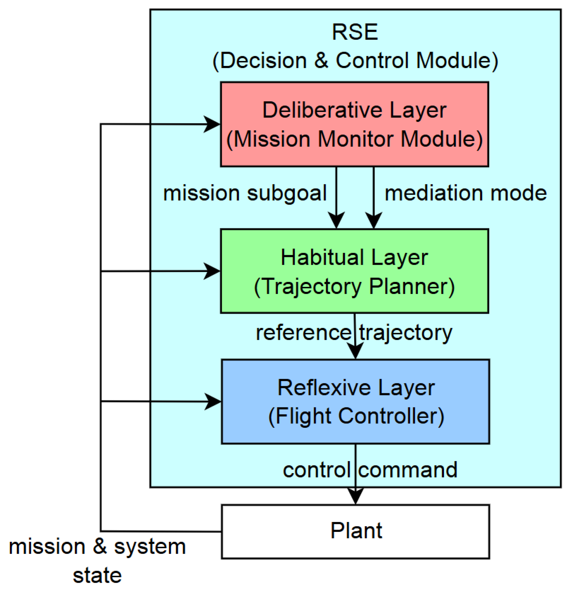
Figure 3.
Simplex at the Reflexive Layer.
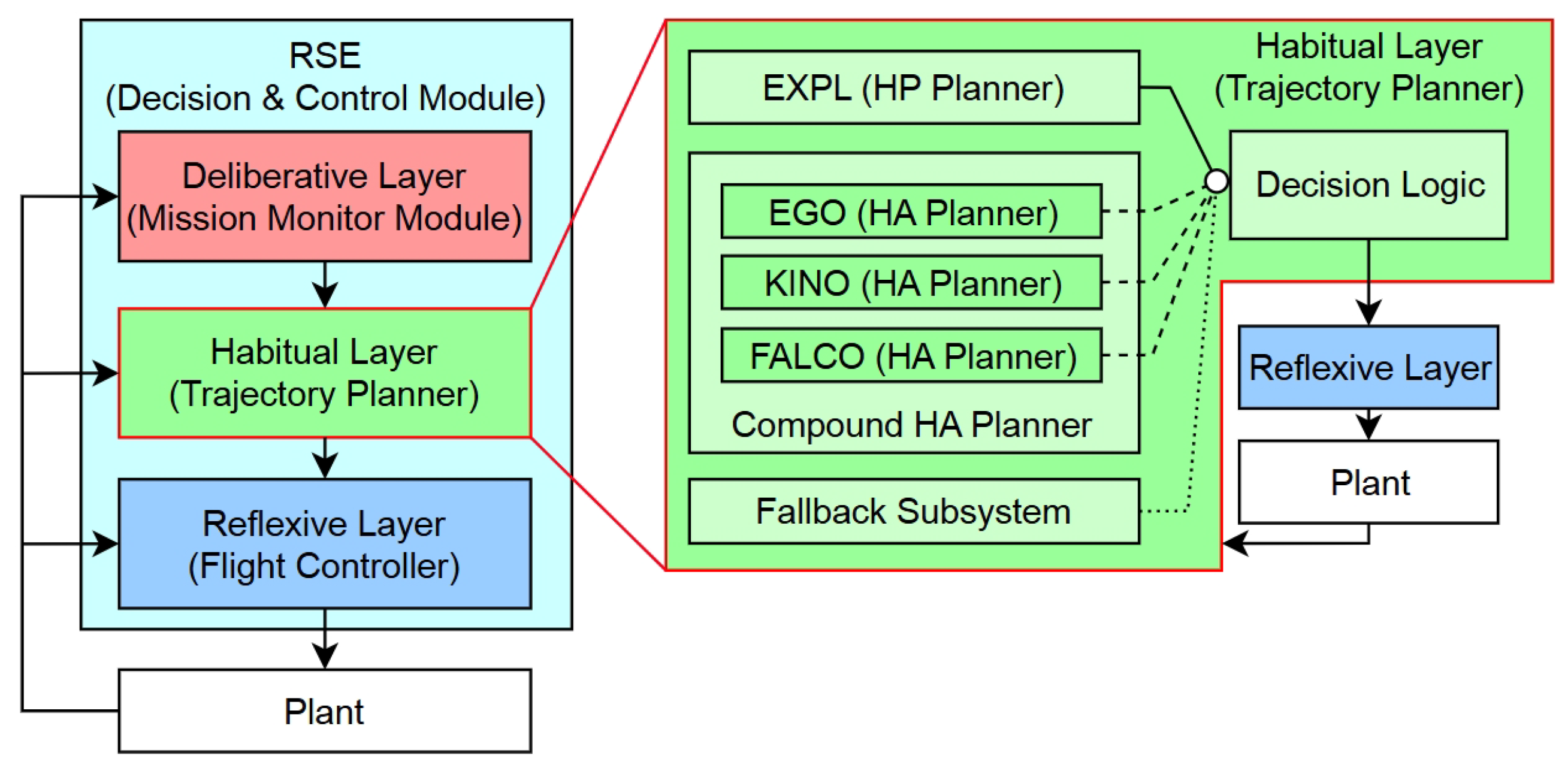
Figure 4.
Simplex in different mediation modes (Habitual Layer).
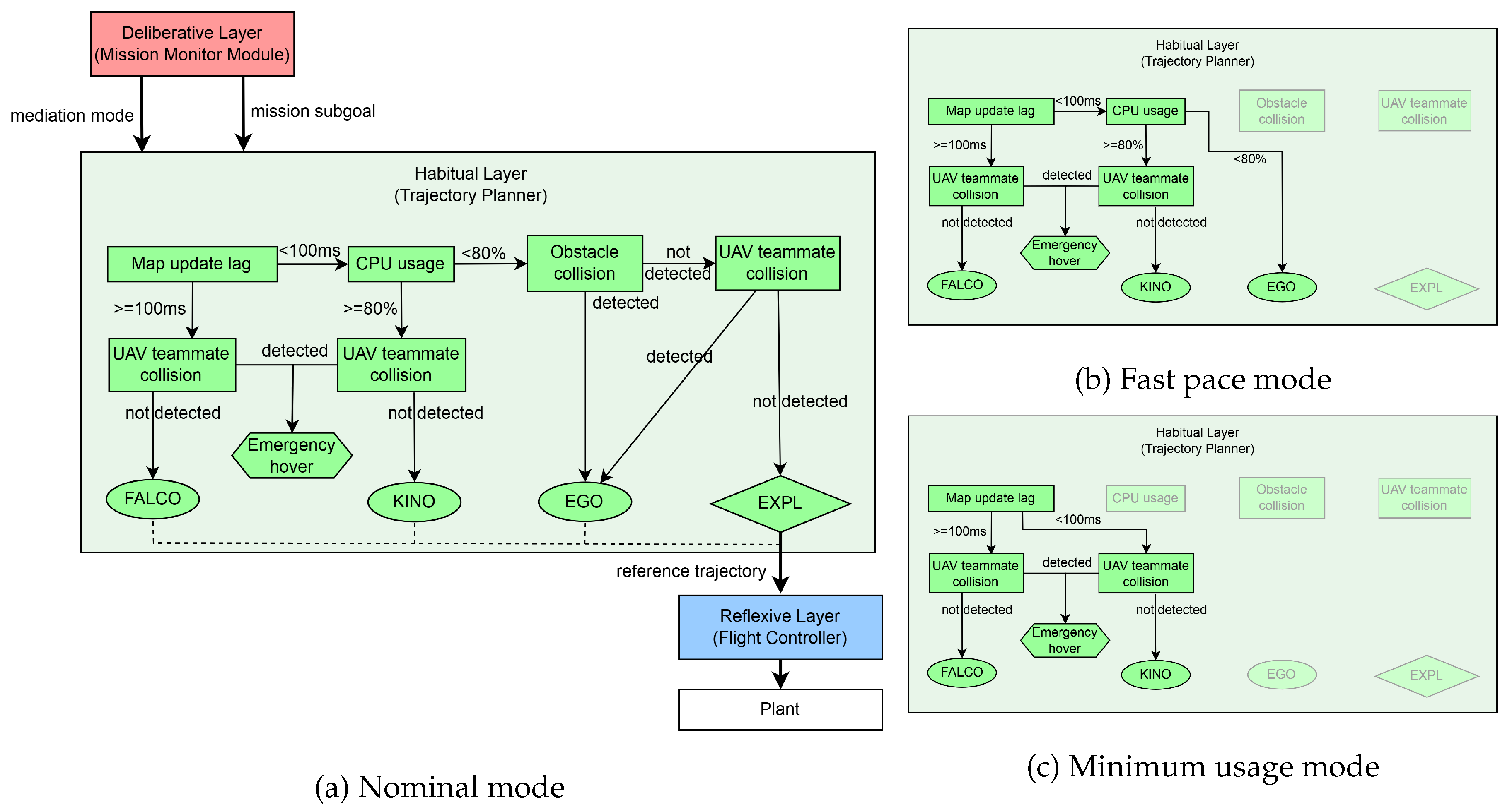
Figure 5.
Simplex at Reflexive Layer.
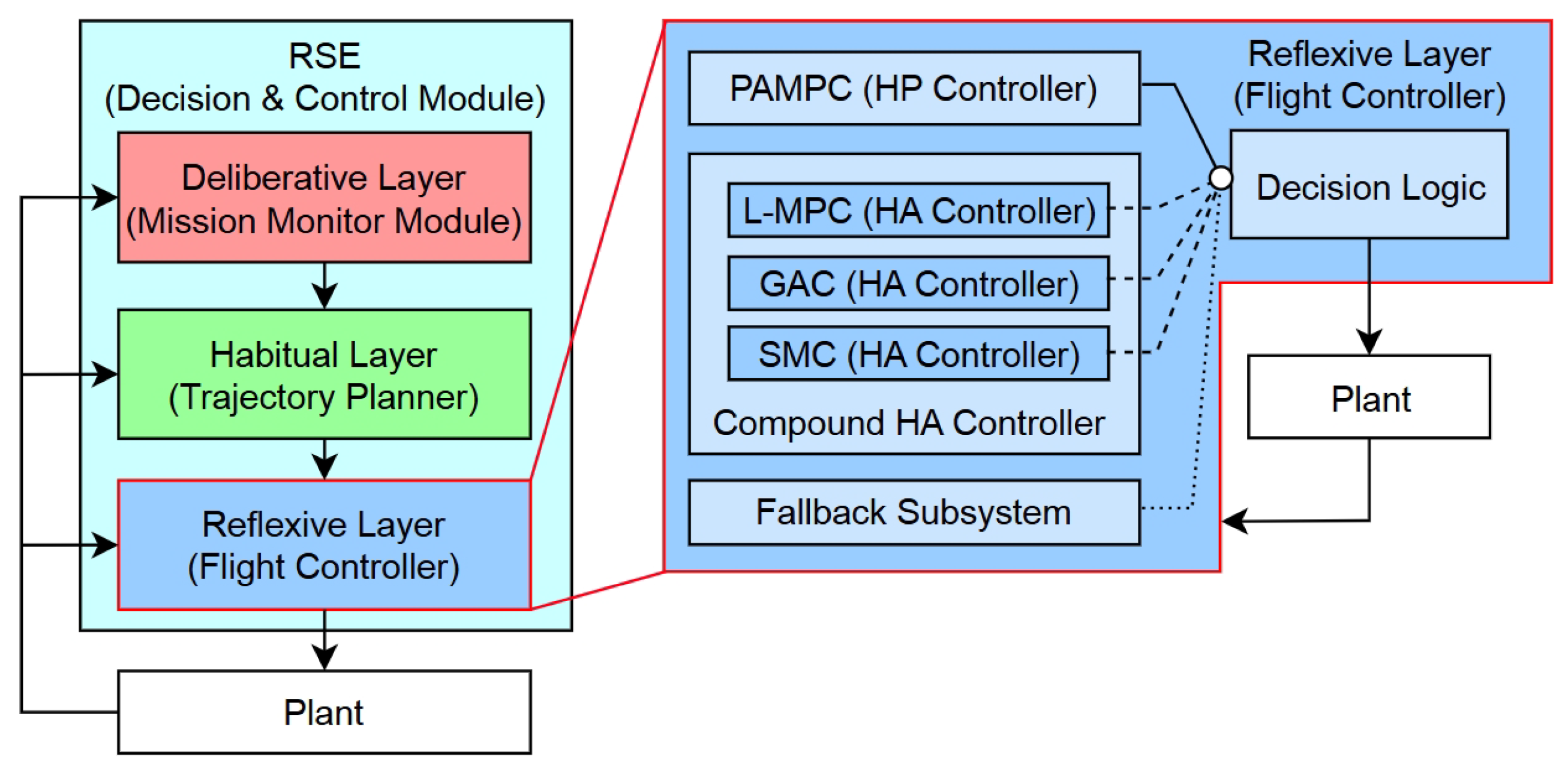
Figure 6.
Simplex in different mediation modes (Reflexive Layer).
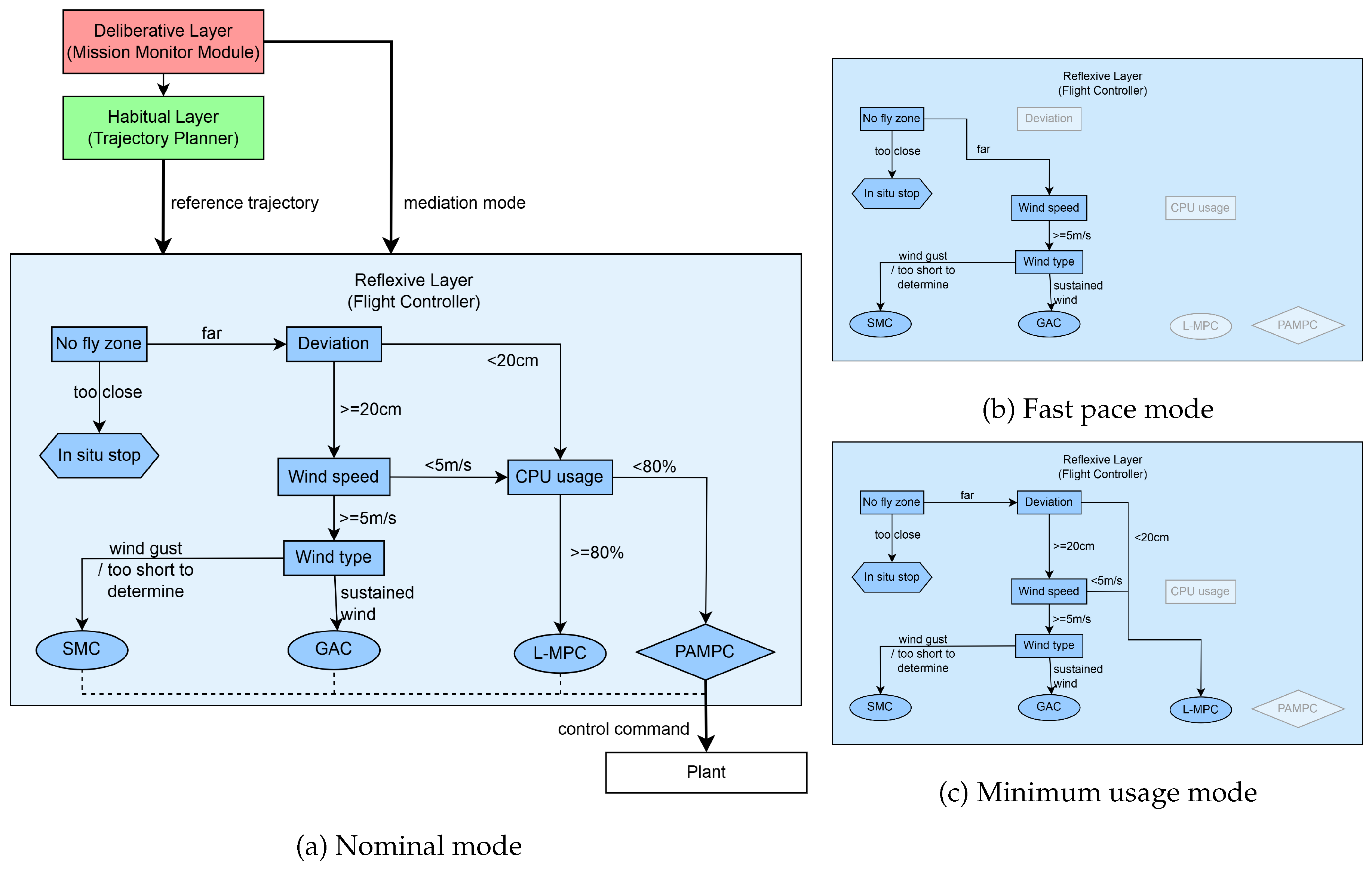
Figure 7.
Pre-acquired point cloud of a bridge.
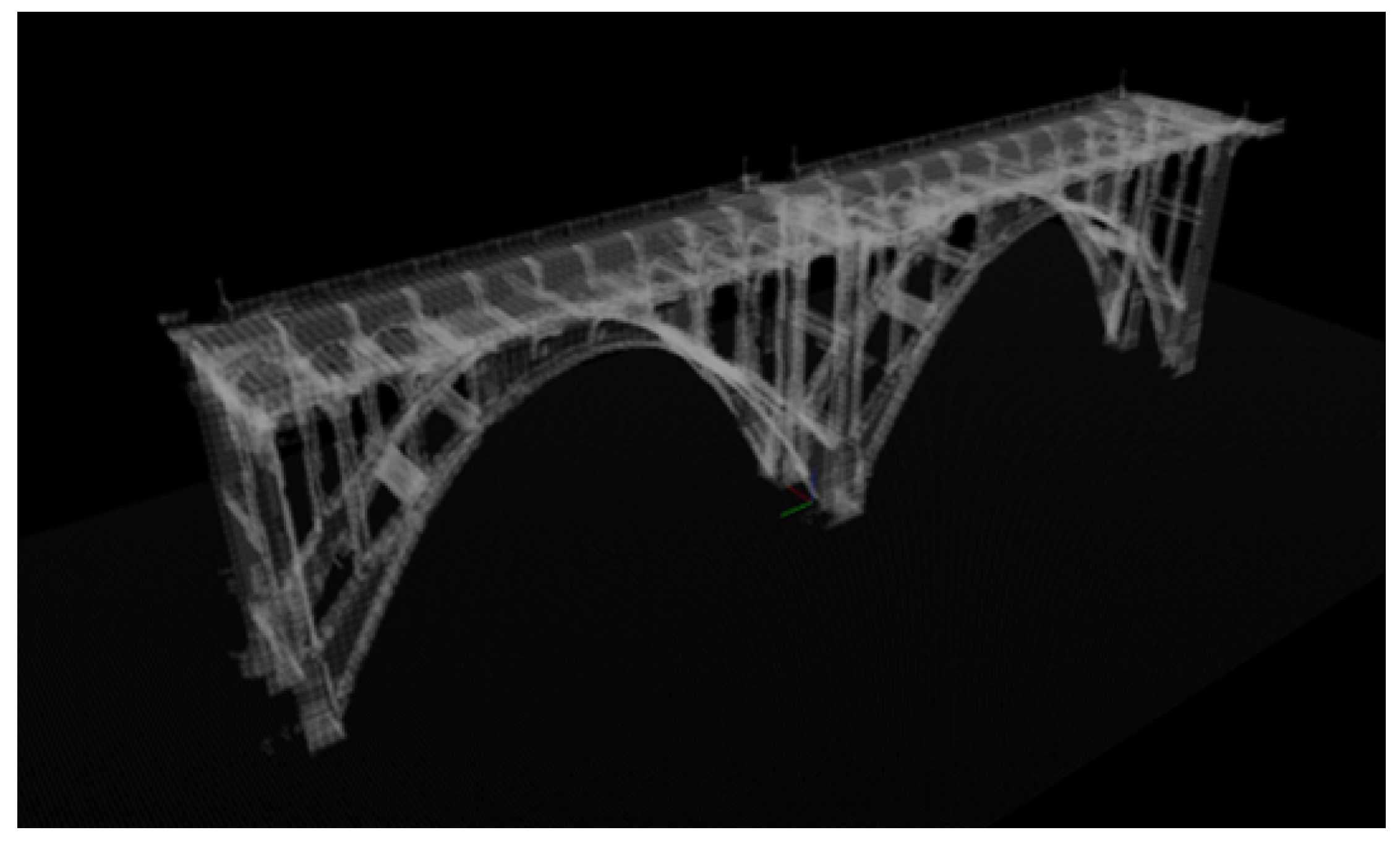
Figure 8.
Rotating stages of the cyclical wind condition.
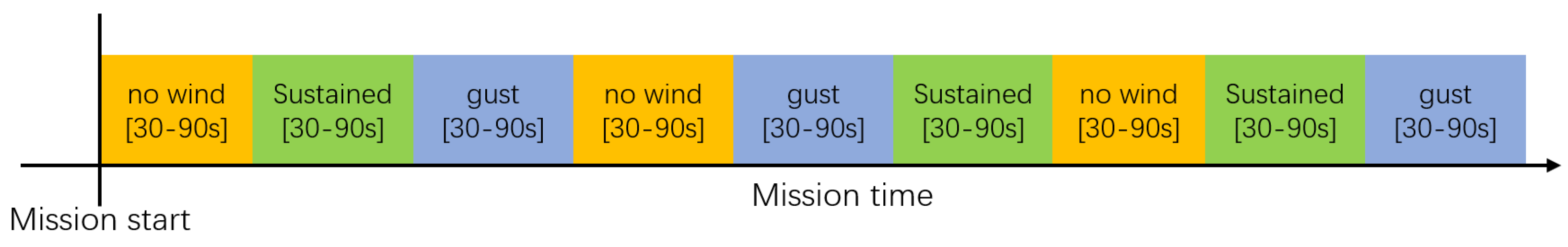
Figure 10.
Comparison of mission performance metrics.
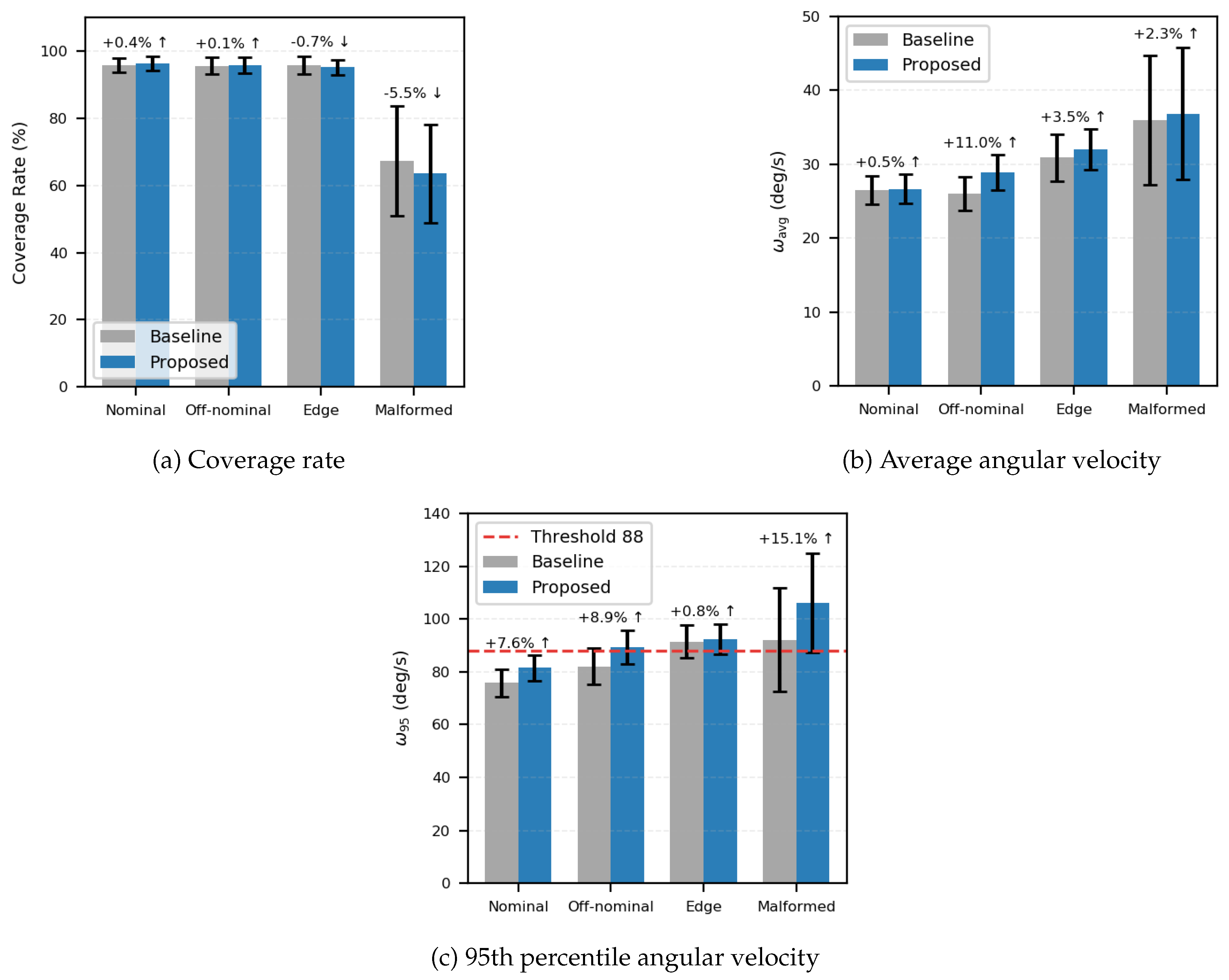
Figure 11.
Comparison of operational assurance metrics.
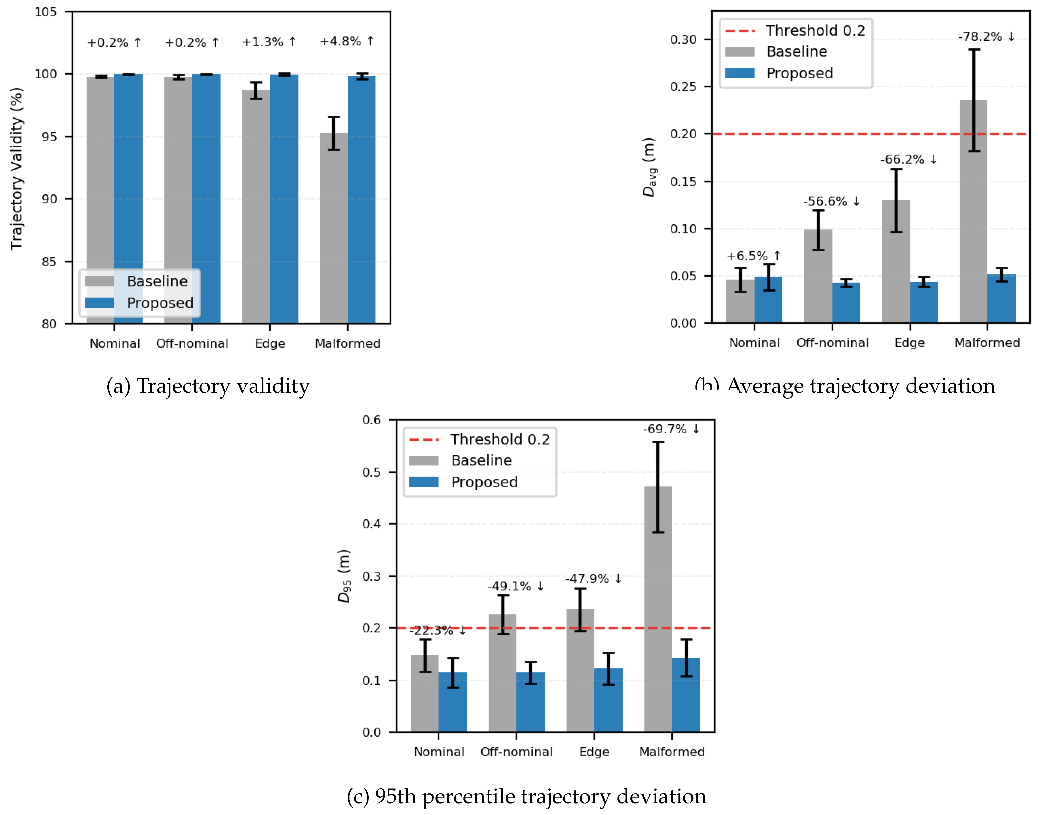
Figure 12.
Comparison with baseline system (edge scenarios).
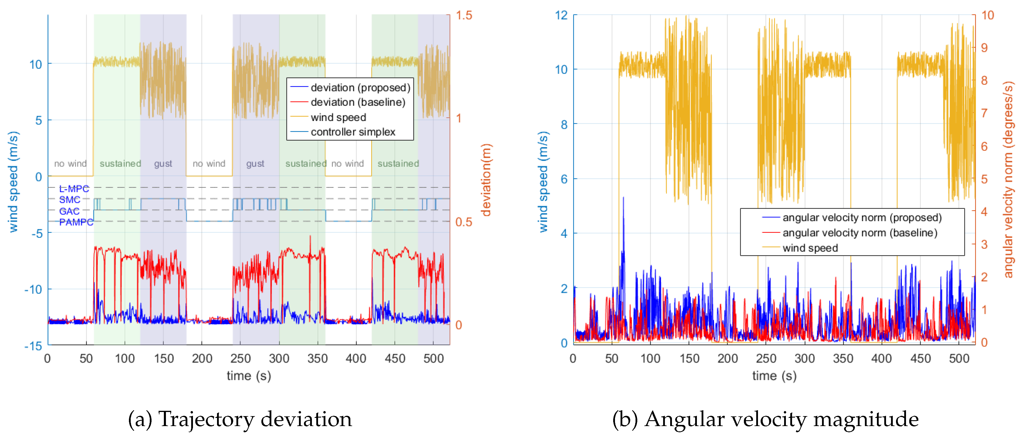
Figure 18.
Executed trajectories (multi-UAV).
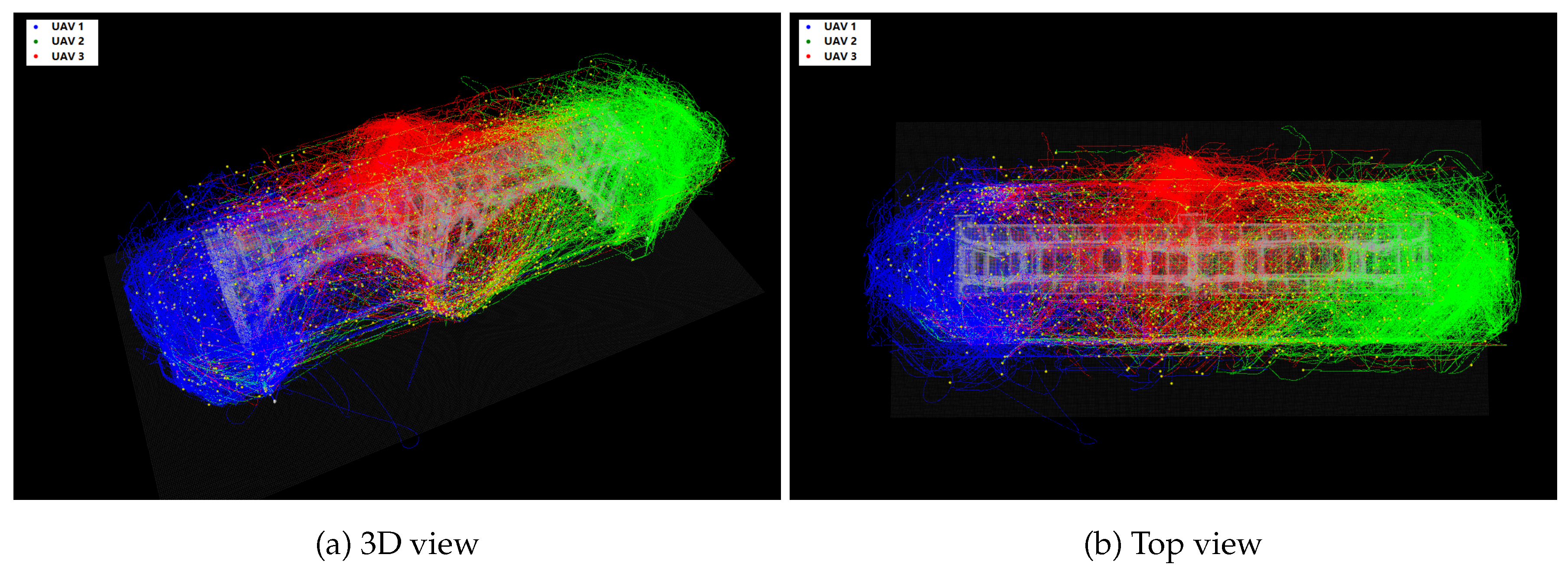
Table 1.
Available trajectory planners in each mediation mode.
| Algorithm | Type | Coverage Rate | Obstacle Avoidance | Need Map | CPU Usage | Nominal Mode | Fast Pace Mode | Min. usage Mode |
| EXPL | HP | High | Low | Yes | Low | Yes | No | No |
| EGO | HA | Mid | Very high | Yes | Mid | Yes | Yes | No |
| KINO | HA | Mid | High | Yes | Low | Yes | Yes | Yes |
| FALCO | HA | Low | High | No | Low | Yes | Yes | Yes |
Table 2.
Available flight controllers in each mediation mode.
| Algorithm | Type | Smoothness | Wind Rejection | CPU Usage | Nominal Mode | Fast Pace Mode | Min. Usage Mode |
| PAMPC | HP | Very high | No | High | Yes | No | No |
| L-MPC | HA | High | No | Low | Yes | No | Yes |
| GAC | HA | Mid | Slow | Low | Yes | Yes | Yes |
| SMC | HA | Low | Fast | Low | Yes | Yes | Yes |
Table 4.
Vehicle obstacle list.
| Condition | Obstacle on top | Obstacle on side |
| Sparse layout | Extended Forklift (1), Mobile Concrete Pump (1) | None |
| Mid layout | Extended Forklift (1), Mobile Concrete Pump (1) | Mobile Drill (1), Extended Mobile Crane (1) |
| Dense layout | Mobile Concrete Pump (1), Mobile Drill (1) | Extended Mobile Crane (1), Crawler Crane (1), Tower Crane (1), Luffing Crane (1) |
| Highly dense layout | Mobile Concrete Pump (1), Mobile Drill (2) | Extended Mobile Crane (2), Crawler Crane (1), Tower Crane (4), Luffing Crane (2) |
Note: The number in parentheses indicates the quantity of each obstacle instance included in the simulation environment.
Table 5.
Mission performance summary.
| Scenarios | Data | Coverage Rate (%) | Average Angular Velocity (deg/s) | 95th Percentile Angular Velocity (deg/s) | Total Time (s) |
| Nominal | Proposed | 96.25 ± 2.09 | 26.66 ± 1.98 | 81.50 ± 4.81 | 526.58 ± 58.85 |
| Baseline | 95.82 ± 2.17 | 26.53 ± 1.93 | 75.76 ± 5.21 | 480.62 ± 55.72 | |
| Off-nominal | Proposed | 95.64± 2.38 | 28.89± 2.40 | 89.38± 6.30 | 530.16± 54.74 |
| Baseline | 95.53± 2.51 | 26.03± 2.28 | 82.06± 6.83 | 526.56± 61.49 | |
| Edge | Proposed | 95.12± 2.31 | 31.98± 2.76 | 92.24± 5.73 | 544.78± 64.04 |
| Baseline | 95.80± 2.68 | 30.90± 3.17 | 91.51± 6.11 | 526.28± 67.92 | |
| Malformed | Proposed | 63.53± 14.59 | 36.84± 8.92 | 106.10± 18.88 | 471.43± 107.06 |
| Baseline | 67.26± 16.38 | 36.01± 8.74 | 92.17± 19.63 | 461.07± 114.22 |
Table 6.
Operational assurance summary.
| Scenarios | Data | Trajectory Validity (%) | Average Trajectory Deviation (m) | 95th Percentile Trajectory Deviation (m) | Total Time (s) |
| Nominal | Proposed | 100.00± 0.03 | 0.049± 0.014 | 0.115± 0.028 | 526.58± 58.85 |
| Baseline | 99.80± 0.08 | 0.046± 0.013 | 0.148± 0.031 | 480.62± 52.31 | |
| Off-nominal | Proposed | 100.00± 0.03 | 0.043± 0.004 | 0.115± 0.021 | 530.16± 54.74 |
| Baseline | 99.80± 0.19 | 0.099± 0.021 | 0.226± 0.037 | 526.56± 61.49 | |
| Edge | Proposed | 99.97± 0.09 | 0.044± 0.005 | 0.123± 0.030 | 544.78± 64.04 |
| Baseline | 98.70± 0.66 | 0.130± 0.033 | 0.236± 0.041 | 526.28± 67.92 | |
| Malformed | Proposed | 99.84± 0.26 | 0.0515± 0.007 | 0.143± 0.035 | 471.43± 107.06 |
| Baseline | 95.30± 1.34 | 0.236± 0.054 | 0.472± 0.087 | 461.07± 114.22 |
Table 7.
Mission performance summary (multi-UAV).
| Scenarios | Data | Coverage Rate (%) | Average Angular Velocity (deg/s) | 95th Percentile Angular Velocity (deg/s) | Total Time (s) |
| Nominal | Proposed | 95.53± 1.30 | 26.80± 1.92 | 85.39± 1.24 | 95.81± 12.63 |
| Off-nominal | Proposed | 95.86± 1.31 | 29.72± 2.80 | 90.37± 2.59 | 98.03± 12.72 |
| Edge | Proposed | 96.48± 2.32 | 33.94± 2.34 | 97.95± 2.70 | 96.61± 12.43 |
| Malformed | Proposed | 76.49± 4.69 | 36.97± 7.33 | 106.79± 16.99 | 191.44± 46.43 |
Table 8.
Operational assurance summary (multi-UAV).
| Scenarios | Data | Trajectory Validity (%) | Average Trajectory Deviation (m) | 95th Percentile Trajectory Deviation (m) | Total Time (s) |
| Nominal | Proposed | 100.00± 0.03 | 0.047± 0.009 | 0.120± 0.023 | 95.81± 12.63 |
| Off-nominal | Proposed | 99.96± 0.16 | 0.053± 0.011 | 0.130± 0.025 | 98.03± 12.72 |
| Edge | Proposed | 99.93± 0.21 | 0.055± 0.010 | 0.138± 0.026 | 96.61± 12.43 |
| Malformed | Proposed | 99.41± 0.63 | 0.066± 0.009 | 0.156± 0.069 | 191.44± 46.43 |
Disclaimer/Publisher’s Note: The statements, opinions and data contained in all publications are solely those of the individual author(s) and contributor(s) and not of MDPI and/or the editor(s). MDPI and/or the editor(s) disclaim responsibility for any injury to people or property resulting from any ideas, methods, instructions or products referred to in the content. |
© 2025 by the authors. Licensee MDPI, Basel, Switzerland. This article is an open access article distributed under the terms and conditions of the Creative Commons Attribution (CC BY) license (http://creativecommons.org/licenses/by/4.0/).
Copyright: This open access article is published under a Creative Commons CC BY 4.0 license, which permit the free download, distribution, and reuse, provided that the author and preprint are cited in any reuse.


