
Submitted:
02 December 2025
Posted:
02 December 2025
You are already at the latest version
Abstract
Asymmetric V-shaped tunnels are commonly found in newly built urban underground road tunnels. During a fire, the smoke flow in such kind of tunnels is complex, and effective smoke control under longitudinal ventilation is challenging. The critical ventilation speed under different slope combinations and fire heat release rate (HRR) in asymmetric V-shaped tunnel with the fire source located at the slope change point were studied by experiments through a 1:20 scaled model tunnel. The research results indicate that the critical ventilation speed increases with the increase of the fire HRR. Under the same fire heat release rate, when longitudinal ventilation is implemented on the side with small slope, the critical ventilation speed decreases as the slope difference between the two sides of the slope change point increases. Conversely, when longitudinal ventilation is implemented from the large slope side, the critical ventilation speed increases with the slope difference increasing. For practical engineering applications, based on the critical ventilation speed of the single-slope tunnel, combining with the experimental results, slope corrections were applied to the critical ventilation velocity of V-shaped tunnels. Calculation models for the critical ventilation velocity under longitudinal ventilation from the large or small slope sides were obtained respectively. The research findings can provide technical support for the design and operation of smoke control systems in V-shaped tunnels during fire incidents.
Keywords:
V-shaped tunnel
; longitudinal ventilation
; critical ventilation speed
; small-scale experiment
1. Introduction
With the rapid development of China's economy, urban transportation land has become increasingly tight. Constructing more underground roads is undoubtedly an effective measure to alleviate urban traffic pressure. Urban underground roads are mostly located in the city center. Due to the influence of the existing underground buildings, such as the existing subways and underground utility tunnels, the longitudinal sections of urban underground roads have become increasingly complex. They are no longer simple horizontal or single-slope tunnels, but present a combination of various continuous V-shaped sections. The complex longitudinal structure increases the probability of traffic accidents and fires caused by vehicles.
Based on whether the slopes on either side of the slope change point are identical, V-shaped tunnels can be classified into symmetrical V-shaped tunnels and asymmetrical V-shaped tunnels [1]. When a fire occurs at the slope change point of a V-shaped tunnel, in symmetric V-shaped sections, smoke generally spreads symmetrically on both sides centered around the slope change point. However, in asymmetric V-shaped tunnels, due to the different slopes on both sides of the slope change point, smoke initially spreads symmetrically from the fire source in the early stages of the fire. As the fire continues, the thermal pressure difference generated by the hot smoke within the tunnel on either side of the slope change point gradually increases. Smoke on the side with the small slope gradually flow towards the slope change point, eventually causing the smoke to flow from the small slope side towards the large slope side. A schematic diagram of smoke spread in a V-shaped tunnel is shown in Figure 1. When the slope difference between the two sides of the slope change point is significant, the smoke may spread entirely within the large slope section. This smoke spread is noticeably different from that in horizontal or single-slope tunnels [1,2].
During tunnel fires, smoke is the main cause of casualties. Generally, the smoke control system in tunnels include longitudinal ventilation smoke control system and point smoke exhaust system [3,4,5]. In longitudinal ventilation smoke control, the critical ventilation velocity is one of the key factors in determining whether the smoke can be effectively controlled. Previous studies have shown that the critical ventilation velocity is mainly influenced by the tunnel's cross-sectional dimensions and the heat release rate of the fire source [4,5,6,7,8,9,10]. For single-slope tunnels, the stack effect induced by the slope has a significant impact on the critical ventilation speed. When the traffic direction is uphill, the critical ventilation speed can be determined using the critical ventilation speed for longitudinal ventilation in a straight and level tunnel under the same fire HRR. When the traffic direction is downhill, the critical ventilation speed value is corrected by slope on the basis of the critical ventilation speed in straight tunnel. The determination of the slope correction coefficient is the key to the calculation of the critical ventilation speed of in slope tunnels. Regarding the slope correction coefficient, many research works have been conducted, and some empirical equations for the slope correction coefficient were obtained [11,12,13,14].
Regarding the critical ventilation speed in tunnels, although there are many available calculation models, most of the current design codes commonly recommend the Kennedy’s model [8] as the calculation model for the critical ventilation speed in the longitudinal ventilation smoke control system design[3,5,15], it can be calculated by
where vc is the critical ventilation speed, m/s;k1 is constant, k1 = 0.606; kg is slope correction coefficient, kg = 1 + 0.0374i0.8, i is the slope of the tunnel, %; h is the height of the tunnel, m; g is the acceleration of gravity, m/s2; Q is the heat release rate of fire, kW; ρ0 is the air density upstream of the fire, kg/m3; cp is the specific heat of the air upstream of the fire, kJ/(kg⋅K); A is the cross section area of the tunnel, m2; Tf is the average temperature of the air close to the fire source, K; T is temperature of the incoming air, K。
However, for asymmetric V-shaped tunnels, due to the existence of the slope change point and the different slope structures on both sides, the critical ventilation speed during longitudinal ventilation smoke control is significantly different from that in single-slope tunnels. For the different traffic direction, longitudinal ventilation may be implemented from the small slope side to the large slope side, or from the large slope side to the small slope side, as shown in Figure 2. In such scenarios, the critical ventilation speed is not only related to the fire HRR and the cross-sectional size of the tunnel, but also to the ventilation position and the slope composition of the tunnel on both sides of the slope change point. Current research on asymmetric V-shaped tunnels predominantly focuses on internal temperature distributions and smoke back-layering length [1,2], with limited studies addressing the critical ventilation velocity under longitudinal ventilation smoke control. Based on this, this study will conduct scaled model experiments to investigate the critical ventilation speed when the fire source is located at the gradient change point, considering various slope combinations on both sides and different heat release rates. The calculation model for the critical ventilation speed in the V-shaped tunnel would be obtained, thereby providing technical support for effectively controlling the smoke during a fire in the V-shaped tunnel.
2. Experimental Studies
2.1. Small scale model tunnel
To investigate the smoke flow and the critical ventilation velocity under longitudinal ventilation in V-shaped tunnel during fire, based on Froude similarity criterion [16], using an urban underground road tunnel in Beijing as the prototype, a scale of 1:20 V-shaped model tunnel was built. The schematic diagram of the model tunnel and the physical model tunnel are shown in Figure 3 and Figure 4 respectively. According to the Froude criterion, the scaling relationships of various physical parameters between the model tunnel and the full-scale tunnel are presented in Table 1.
The length of the model tunnel is 20.5m, with a cross-sectional dimension of 0.675 m × 0.5 m (width × height). The main body of the model tunnel consists of a 0.5 m long fire source section in the middle and two adjustable slope sections on both sides, each with a length of 10 m. In order to observe the smoke spread during experiments and arrange the thermocouples, three sides of the standard sections are covered with galvanized steel plates, and the inner side is lined with 2 mm-thick asbestos fireproof boards. The front of the model tunnel is equipped with fireproof glass doors. To achieve slope adjustments on both sides of the tunnel, manual chain hoists are suspended at intervals above the tunnel on both sides, allowing the slope of the two sides to be adjusted by lifting or lowering the double chain wheels, with an adjustment range of 0~10°.
The fuel used for the experiment is liquefied petroleum gas (LPG). Change of HRR during experiments are achieved by adjusting the flow rate of the liquefied petroleum gas. The density of the liquefied petroleum gas used in the experiments is 2.35 kg/m³, with a combustion heat value of 43.7 MJ/kg. The dimensions of the fire burner are 0.15m × 0.10m × 0.06m (length × width × height). When longitudinal ventilation is implemented in the tunnel, the fan is positioned at the end of the tunnel with a large slope or a small slope as needed. A rectification device is installed at the front of the fan. Longitudinal ventilation speed change is achieved through changing the frequency of the fan.
In the experiment, the critical ventilation speed was determined as the ventilation speed at which the smoke back-layer length upstream of the fire source observed through the light sheet reduced to zero. The arrangement of the ventilation speed measurement points is shown in Figure 3. Ventilation speed was measured using a TES-1340 Hot-Wire Anemometer (TES Electrical Electronic Corp.), the accuracy of the anemometer is ±3% of reading ±1% of full scale, and its resolution is 0.01m/s.
2.2. Experimental Scenarios
With reference to the provisions on tunnel slopes in tunnel design guides, based on investigations of actual tunnel roads, the slopes of the tunnels currently in operation in China are mainly concentrated between 1% and 5%. A small number of tunnels may have local gradients exceeding 7% due to terrain constraints and the influence of existing structures. To further study the effectiveness of smoke control in longitudinal ventilation systems under different slope combinations, several slope combinations such as 1%, 3%, 5% and 7% were selected on both sides of the V-shaped tunnel slope change point in the experiments. Since heavy goods vehicle (HGV) are mostly prohibited in urban tunnels, the maximum designed fire heat release rate under fire conditions generally does not exceed 30 MW[3,4,5]. To study the influence of HRR on critical ventilation speed, the fire powers of 5MW, 20MW and 30MW were selected, and the corresponding HRR in the model experiments was 2.8kW, 11.18kW and 16.67kW respectively. Depending on the direction of traffic flow, the implementation of longitudinal ventilation in the asymmetric V-shaped tunnel may be carried out on the side with a small slope or on the side with a large slope. The experimental scenarios are shown in Table 2. To make the analysis of the experimental results more explicit, the working condition where longitudinal induced wind is applied on the small slope side is set as number S, and the working condition where longitudinal induced wind is applied on the large slope side is set as L.
3. Results and Discussions
Figures 5a and 5b present the changes in critical ventilation velocity under different slope combinations and fire HRR when longitudinal ventilation is applied from the side with large slope and from the side with small slope respectively. It can be seen from the figure that regardless of whether longitudinal ventilation is implemented from the large slope side or the small slope side, the critical ventilation speed increases with the increase of the fire power. For the same fire power and slope configuration, the critical ventilation speed for longitudinal ventilation implemented from the large slope side is much greater than that for longitudinal ventilation implemented from the small slope side. This is because when longitudinal ventilation is implemented from the side with large slope, greater thermal pressure must be overcome in order to effectively control the smoke backflow. Figure 6 shows the influence of the slope of the large slope side on the critical ventilation speed under different fire HRR. It can be observed that when longitudinal ventilation is implemented from the small slope side, the critical ventilation speed decreases as the slope on the large slope side increases. When longitudinal ventilation is implemented from the large slope side, the critical ventilation speed increases with the increase of the large slope side. This is because when longitudinal ventilation is implemented from the small slope side, the thermal pressure difference on both sides of the slope change point promotes smoke backflow toward the fire source. Moreover, as the slope difference increases, the thermal pressure difference gradually increases, causing the critical ventilation speed to gradually decrease. On the other hand, when ventilation is applied from the large gradient side, the direction of the thermal pressure difference between the large and small slope sides opposes the longitudinal airflow, requiring a higher airflow velocity to contain the smoke at the fire source and prevent backflow.
Figure 7 presents a comparison of the critical ventilation speed when longitudinal ventilation is implemented from the large slope side at the slope of 5% and the critical ventilation speed in a single-slope tunnel with a 5% gradient when vehicles are moving downhill. As shown in the figure, due to the presence of the slope on the small gradient side and the influence of local resistance at the slope change point, the critical ventilation speed for longitudinal ventilation implemented on the large slope side of the asymmetric V-shaped tunnel is greater than that of the single-slope tunnel. Figure 8 shows a comparison of the critical ventilation velocity when longitudinal ventilation is implemented on the small slope side with a slope of 1% and the critical ventilation speed in a single slope tunnel with a 1% gradient when vehicles are moving downhill. The results indicate that when the slope difference on both sides of the slope change point is about 4%, the critical ventilation speed for ventilation for implementing longitudinal ventilation on the small slope side is equivalent to that of a single-slope tunnel with a slope of 1%. When the slope difference on both sides of the slope change point is greater than 4%, the critical ventilation speed when longitudinal ventilation is implemented on the small slope side is less than that of a single-slope tunnel with the same slope. When the slope difference is less than 4%, the critical ventilation speed for implementing longitudinal ventilation on the small slope side is greater than that of a single slope tunnel with the same slope. This is mainly because when the slope difference on both sides of the slope change point is large, the thermal pressure difference between the two sides plays a dominant role. This pressure difference causes more smoke to flow toward the large slope side, thereby reducing the critical ventilation velocity required on the small gradient side compared to a single slope tunnel. When the slope difference is less than 4%, the local resistance at the slope change point becomes the primary factor. In this case, a higher airflow velocity is required to prevent smoke backflow compared to a single slope tunnel, resulting in a higher critical ventilation velocity.
For the convenience of engineering use, taking the critical ventilation speed of the single-slope tunnel as the reference speed, assuming the ratio of the critical ventilation speed when longitudinal ventilation is implemented on the large gradient side to the critical velocity of a single-slope tunnel with the same gradient is kl,and the ratio of the critical ventilation speed when longitudinal ventilation is applied on the small gradient side to the critical velocity of a single-slope tunnel with the same gradient is ks, the critical ventilation speeds from the large slope side vcVl and the critical ventilation speeds from the small slope side vcVs in V-shaped tunnel can be expressed respectively as
Where vcl is the critical ventilation speed of a single slope tunnel with the slope same as that of the large slope in V-shaped tunnel, m/s; vcs is the critical ventilation speed of a single slope tunnel with the slope same as that of the small slope in V-shaped tunnel, m/s。
Figure 9 shows the variation of the correction coefficient kl for the large slope side with the slope difference on both sides of the slope change point. It can be seen from the figure that kl increases with the increase of the slope difference. Through data fitting, kl can be expressed by:
Figure 10 shows the variation of the correction coefficient ks for the small slope side with the slope difference on both sides of the slope change point. It can be seen from the figure that ks decreases with the increase of the slope difference. Through data fitting, ks can be expressed by:
Based on the above correction coefficients, the critical ventilation speed in asymmetric V-shaped tunnel can be calculated by the following equations.
- (1)
- For critical ventilation speed from the small slope side, vcVs can be calculated by
- (2)
- For critical ventilation speed from the large slope side, vcVl can be calculated by
The relative errors obtained by comparing the critical ventilation speed calculated by equation (7) and(8)with the experimental results are shown in Table 3, where . As can be seen from the table, all errors are within 10%, meeting the requirements for engineering application.
4. Conclusions
The critical ventilation speed when longitudinal ventilation is implemented in an asymmetric V-shaped tunnel under the influence of different fire source powers and slope compositions when the fire source is located at the slope change point were investigated through the model experiments. The following conclusions can be drawn:
(1) The critical ventilation speed in the V-shaped tunnels increases with the rise in the fire heat release rate;
(2) For the same fire power and slope composition, the critical ventilation speed when longitudinal ventilation is implemented from the large slope side is much greater than that when longitudinal ventilation is implemented from the small slope side. When longitudinal ventilation is implemented from the small slope side, the critical ventilation speed decreases as the slope on the side with large slope increases. When critical ventilation speed is implemented on the large slope side, the critical ventilation speed increases as the slope of the small slope side increases.
(3) Due to the influence of local resistance at the slope change point and the thermal pressure difference caused by the asymmetric slopes on both sides, when longitudinal ventilation is applied from the small slope side, there is a critical slope difference compared with the critical ventilation speed of the single-slope tunnel. Greater than this slope difference, the critical ventilation speed on the small slope side is less than that in the single-slope tunnel with same slope; conversely, the critical ventilation speed on the small slope side is greater than that in the single slope tunnel. When longitudinal ventilation is applied from the side with large slope, the critical ventilation speed is greater than that of a single slope tunnel with the same slope.
(4) Based on theoretical analysis and experimental results, the empirical equations of the critical ventilation speed in V-shaped tunnels were obtained as:
a) For critical ventilation speed from the small slope side
b) For critical ventilation speed from the large slope side
The findings of this study are applicable to asymmetrical V-shaped tunnels with slope combinations ranging from 1% to 7% on both sides of the slope change point. There are many factors influencing the critical ventilation speed in V-shaped tunnels. Besides the composition of the slope and the fire HRR, the location of the fire source and the length of the tunnel also have a significant impact. Further theoretical analysis and related experimental research on the critical ventilation velocity and smoke flow characteristics within V-shaped tunnels will be continued in subsequent studies.
Author Contributions
Conceptualization, Junmei Li. and Yanfeng Li.; methodology, Junmei Li; formal analysis, Hengxuan Zhao.; investigation, Hengxuan Zhao; Wenbo Liu; data curation, Hengxuan Zhao.; writing—original draft preparation, Junmei Li; Hengxuan Zhao and Wenbo Liu; writing—review and editing, Junmei Li and Yanfeng Li.; supervision, Yanfeng Li. All authors have read and agreed to the published version of the manuscript.
Funding
This research was funded by the Beijing Natural Science Foundation (Grant no. 8222002).
Data Availability Statement
The data presented in this study are available on request from the corresponding author.
Conflicts of Interest
The authors declare no conflicts of interest.
References
- Dong Q.; Li J.;, Li Y.; Lu H.; Zhao H. Experimental study of the influence of an asymmetric tunnel structure on the maximum ceiling temperature in a V-Shaped tunnel fire. Fire, 2024, 7, 483.
- Tu D.; Li J.; Li Y.; Xu D. Numerical study on the influence of the slope composition of the asymmetric V-shaped tunnel on smoke spread in tunnel fire. Fire, 2024, 7, 363.
- World Road Association. Fire and smoke control in road tunnels. World Road Association, 1999.
- China Merchants Chongqing Communications Technology Research & Design Institute Co. Ltd. JTG/T D70/2-02-2014 Guidelines for Design of Ventilation of Highway Tunnels. People's Communications Publishing House Co., Ltd, Beijing, China, 2014 (in Chinese).
- Shanghai Tunnel Engineering & Rail Transit Design and Research Institute. DG/TJ08-2033-2017 Road Tunnel Design Code. Tongji University Press, Shanghai, China, 2017 (in Chinese).
- Thomas P.H. The movement of buoyant fluid against a stream and the venting of underground fires.Fire Research Station,UK, 1958.
- Thomas P.H. The movement of smoke in horizontal passages against an air flow. Fire Research Station, UK, 1968.
- Danziger N.H.; Kennedy W.D. Longitudinal ventilation analysis for the Glenwood canyon tunnels. Proceedings of the 4th International Symposium of Aerodynamics and Ventilation of Vehicle Tunnels, York, UK, 1982, 169-186.
- Oka Y.; Atkinson G.T. Control of smoke flow in tunnel fires. Fire Saf. J. 1995,25( 4) : 305-322.
- Wu Y.; Bakar M.Z.A. Control of smoke flow in tunnel fires using longitudinal ventilation systems - a study of the critical velocity. Fire Saf. J. 2000, 4( 35) : 363-390. [CrossRef]
- Atkinson G.; Wu Y. Smoke control in slopping tunnels. Fire Saf. J. 1996, 27: 335-341.
- Chow W.K.; Gao Y.; Zhao J. H. et al. Smoke movement in titled tunnel fires with longitudinal ventilation. Fire Saf. J., 2015, 75: 14-22. [CrossRef]
- Li J.; Li Y.F.; Cheng C.H.; Chow W.K. A study on the effects of the slope on the critical velocity for longitudinal ventilation in titled tunnels. Tunn. Undergr. Space Technol. 2019, 89: 262-267. [CrossRef]
- Yi L.; Xu Q.; Xu Z. et al. An experimental study on critical velocity in sloping tunnel with longitudinal ventilation under fire. Tunn. Undergr. Space Technol. 2014, 43: 198-203.
- CJJ 221-2015, Code for design of urban underground road engineering. Ministry of Houseing and Urban-Rural Development of the People’s Republic of China, 2015(in Chinese).
- NFPA 92, Standard for smoke control system. National Fire Protection Association, Quincy, Massachusetts, USA, 2018.
Figure 1.
Schematic diagram of smoke spread in V-shaped tunnel fire
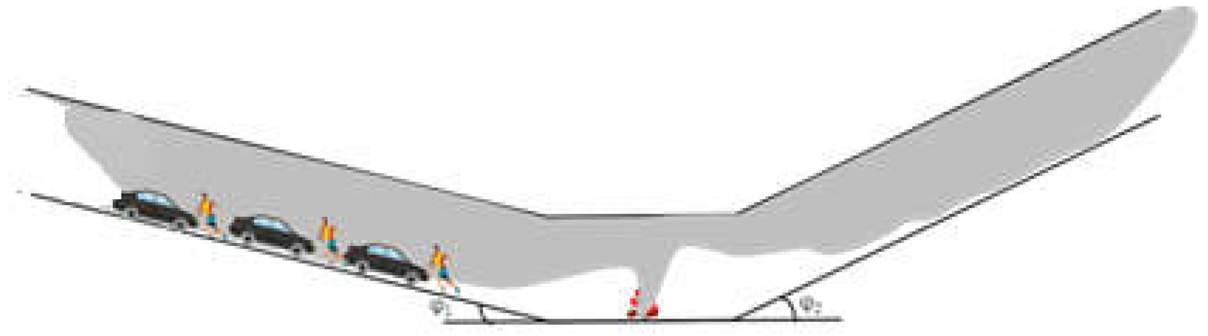
Figure 2.
Schematic description of longitudinal ventilation in a V-shaped tunnel for different traffic directions
Figure 2.
Schematic description of longitudinal ventilation in a V-shaped tunnel for different traffic directions
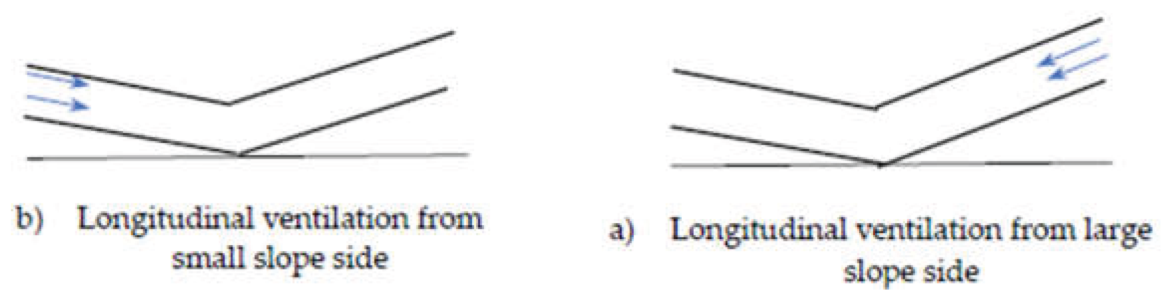
Figure 3.
The schematic diagram of the V-shaped model tunnel experimental system.
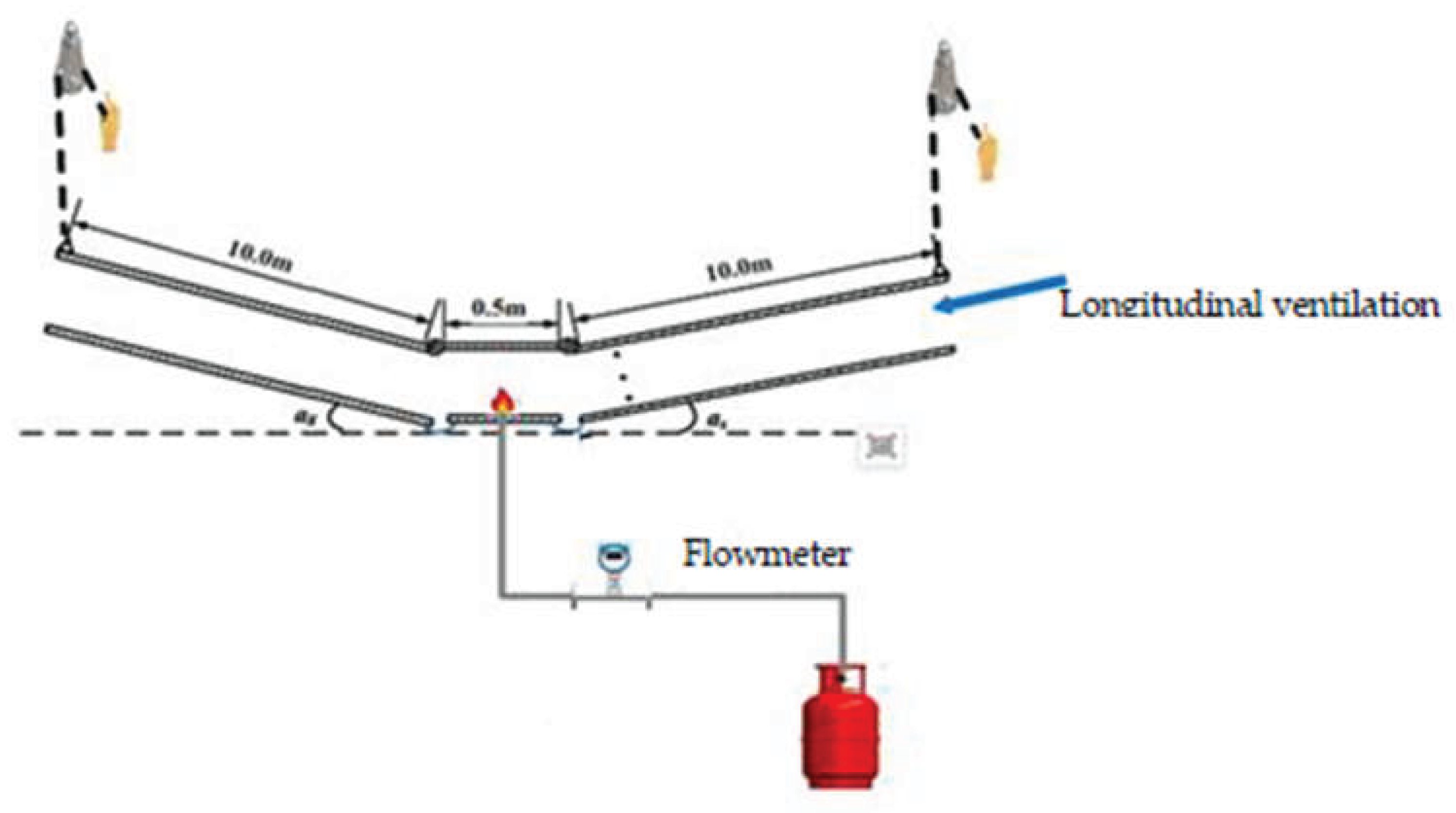
Figure 4.
V-shaped scaled model tunnel.
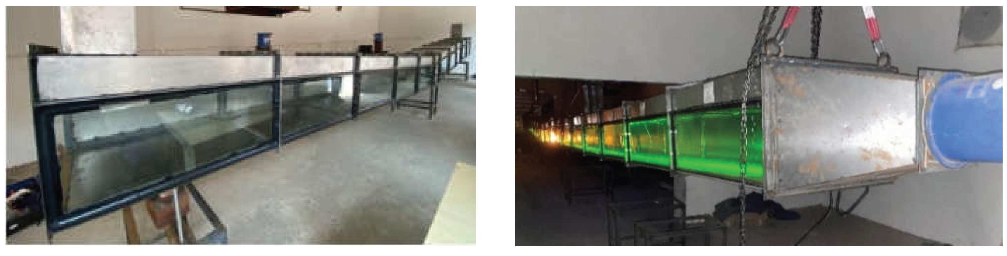
Figure 5.
Variation of the critical ventilation speed with fire HRR
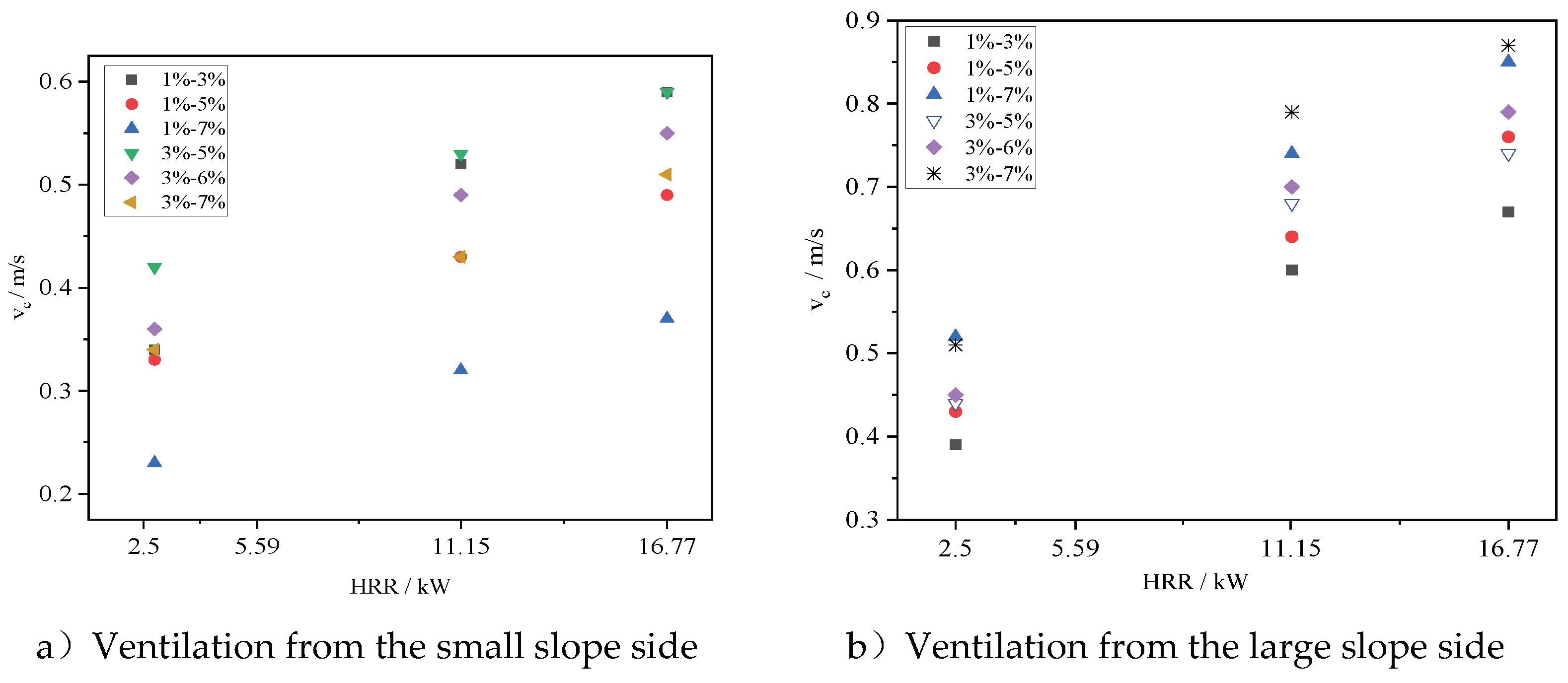
Figure 6.
Variation of the critical ventilation speed with the slope of the large slope in V-shaped tunnel
Figure 6.
Variation of the critical ventilation speed with the slope of the large slope in V-shaped tunnel
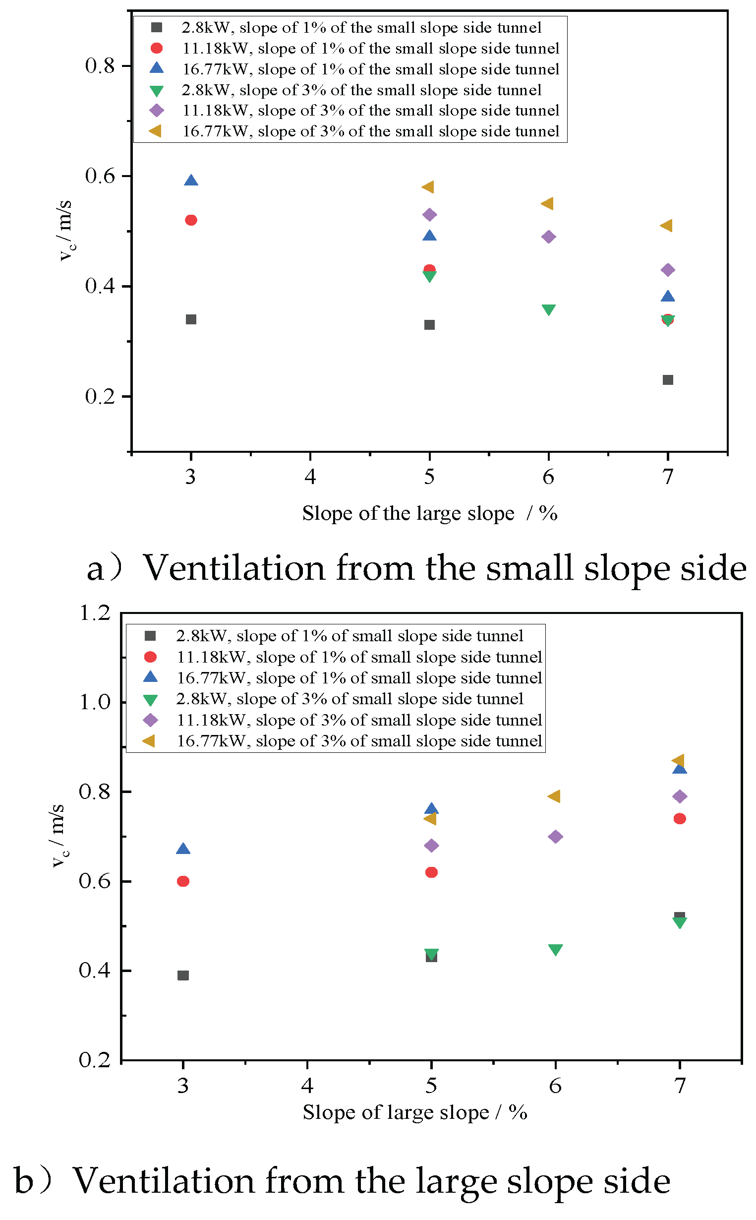
Figure 7.
Comparison of the critical ventilation speed at large slope side with a slope of 5% and that of a single-slope tunnel with same slope.
Figure 7.
Comparison of the critical ventilation speed at large slope side with a slope of 5% and that of a single-slope tunnel with same slope.
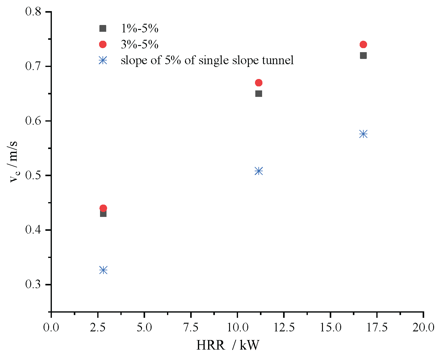
Figure 8.
Comparison of the critical ventilation speed at small slope side with a slope of 1% and that of a single-slope tunnel with same slope.
Figure 8.
Comparison of the critical ventilation speed at small slope side with a slope of 1% and that of a single-slope tunnel with same slope.
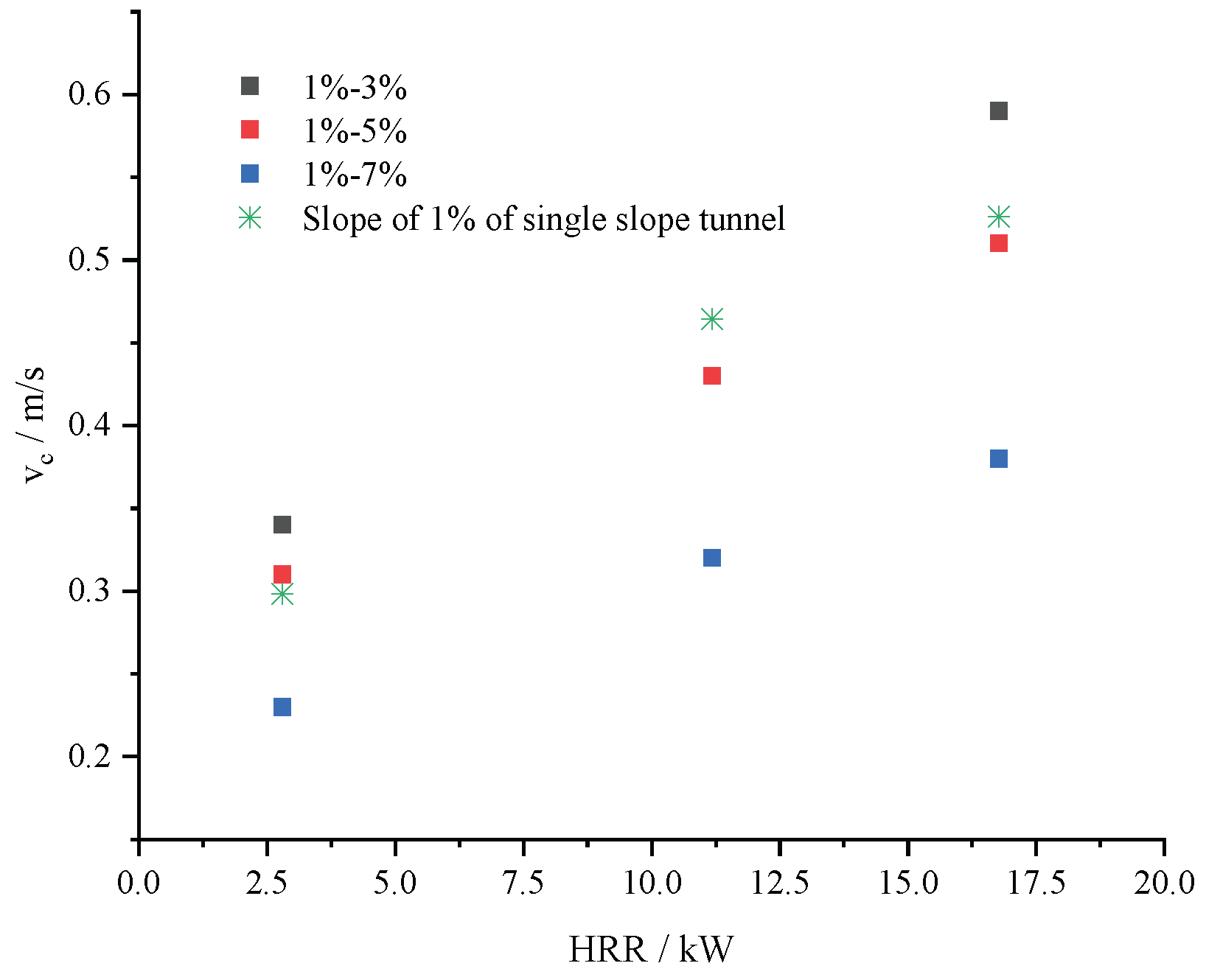
Figure 9.
Variation of kl with the slope difference on both sides of the slope change point
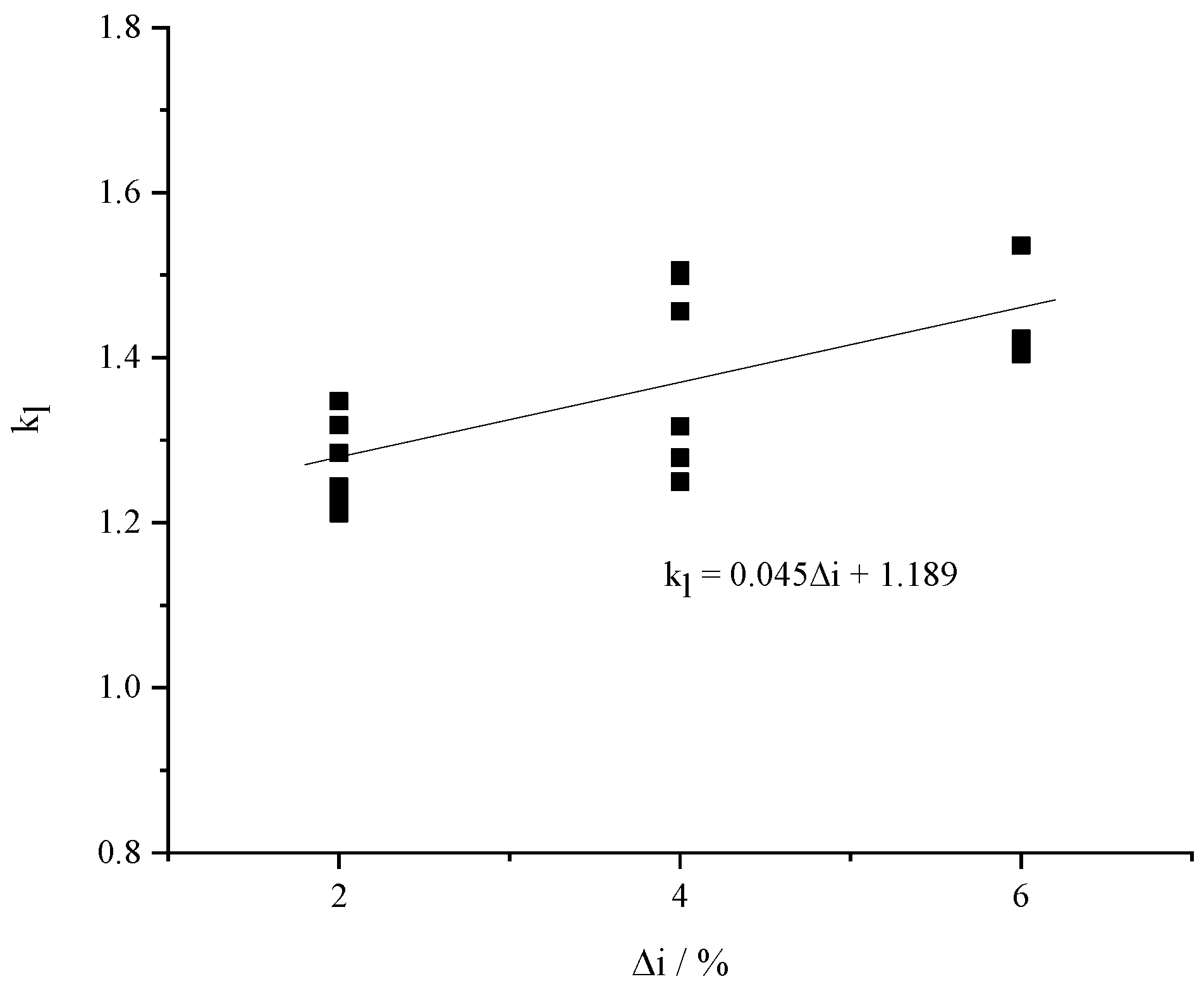
Figure 10.
Variation of ks with the slope difference on both sides of the slope change point
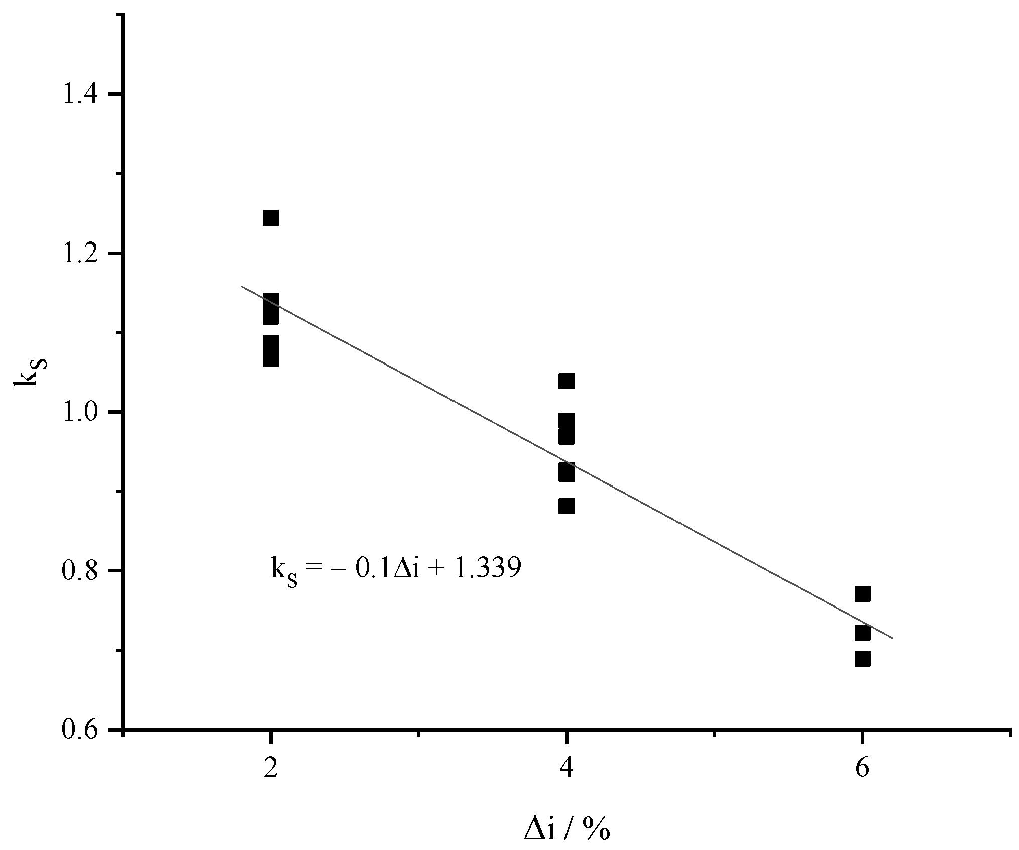

Table 1.
Scaling expressions.
| Variable | Expression |
|---|---|
| Position or length | |
| Temperature | |
| Velocity | |
| Heat release rate | |
| Volumetric flow rate |
Where subscripts: f = full scale; m = small scale model
Table 2.
Experimental scenarios.
| Longitudinal ventilation from the small slope side | Longitudinal ventilation from the large slope side | ||||
| Scenario number | Fire HRR | Slope combination | Scenario number | Fire HRR | Slope combination |
| S-1 | 2.8kW | 1%-3% | L-1 | 2.8kW | 1%-3% |
| S-2 | 1%-5% | L-2 | 1%-5% | ||
| S-3 | 1%-7% | L-3 | 1%-7% | ||
| S-4 | 3%-5% | L-4 | 3%-5% | ||
| S-5 | 3%-6% | L-5 | 3%-6% | ||
| S-6 | 3%-7% | L-6 | 3%-7% | ||
| S-7 | 11.18kW | 1%-3% | L-7 | 11.18kW | 1%-3% |
| S-8 | 1%-5% | L-8 | 1%-5% | ||
| S-9 | 1%-7% | L-9 | 1%-7% | ||
| S-10 | 3%-5% | L-10 | 3%-5% | ||
| S-11 | 3%-6% | L-11 | 3%-6% | ||
| S-12 | 3%-7% | L-12 | 3%-7% | ||
| S-13 | 16.77kW | 1%-3% | L-13 | 16.77kW | 1%-3% |
| S-14 | 1%-5% | L-14 | 1%-5% | ||
| S-15 | 1%-7% | L-15 | 1%-7% | ||
| S-16 | 3%-5% | L-16 | 3%-5% | ||
| S-17 | 3%-6% | L-17 | 3%-6% | ||
| S-18 | 3%-7% | L-18 | 3%-7% | ||
Table 3.
Relative errors between the calculated critical ventilation speed and the experimental results.
Table 3.
Relative errors between the calculated critical ventilation speed and the experimental results.
| Fire HRR | Slope composition | Relative error of the critical ventilation speed from small slope side | Relative error of the critical ventilation speed from large slope side | |
|---|---|---|---|---|
| 2.28kW | 1%-3% | -0.13% | 2.85% | |
| 1%-5% | -9.83% | 4.07% | ||
| 1%-7% | -4.56% | -4.85% | ||
| 3%-5% | -8.51% | -5.03% | ||
| 3%-7% | -5.25% | -9.02% | ||
| 11.18kW | 1%-3% | 1.63% | 4.05% | |
| 1%-5% | 1.17% | 7.15% | ||
| 1%-7% | 6.75% | 4.05% | ||
| 3%-5% | 4.77% | -2.94% | ||
| 3%-7% | 6.31% | -8.59% | ||
| 16.67kW | 1%-3% | 1.54% | 5.63% | |
| 1%-5% | -3.30% | 9.66% | ||
| 1%-7% | 1.91% | 2.69% | ||
| 3%-5% | 6.69% | -0.38% | ||
| 5%-7% | 1.61% | -5.90% |
Disclaimer/Publisher’s Note: The statements, opinions and data contained in all publications are solely those of the individual author(s) and contributor(s) and not of MDPI and/or the editor(s). MDPI and/or the editor(s) disclaim responsibility for any injury to people or property resulting from any ideas, methods, instructions or products referred to in the content. |
© 2025 by the authors. Licensee MDPI, Basel, Switzerland. This article is an open access article distributed under the terms and conditions of the Creative Commons Attribution (CC BY) license (http://creativecommons.org/licenses/by/4.0/).
Copyright: This open access article is published under a Creative Commons CC BY 4.0 license, which permit the free download, distribution, and reuse, provided that the author and preprint are cited in any reuse.


