
Submitted:
01 December 2025
Posted:
02 December 2025
You are already at the latest version
Abstract
The pitting corrosion resistance and the tribological behaviour of a ferritic stainless steel with high Mo content (AISI 436) and a commonly employed austenitic stainless steel (AISI 304) are compared. Special attention was paid to the role of Mo in improving corrosion resistance of ferritic stainless steels. Since the surface condition is an important parameter related to the onset of pitting corrosion in the presence of chlorides, three different surface finishes were tested for both steels. Two commercial finishing grades and laboratory polishing down to 1 µm were compared. Moreover, the influence of surface condition on the tribological properties for both steels was also evaluated. The study demonstrates that surface finishing plays a decisive role in both the electrochemical and mechanical response of stainless steels. A comprehensive microstructural and tribological analysis reveals not only how commercial finishing treatments modify passive film behaviour, but also how they affect friction stability and wear mechanisms. Special emphasis is placed on the synergistic effect between molybdenum content, passive film integrity and manufacturing processes. The obtained results provide valuable insight for industrial applications where durability against chloride exposure and abrasion is critical.
Keywords:
stainless steel
; pitting corrosion
; wear behavior
; 2B condition
; BA condition
1. Introduction
Austenitic stainless steels are the most popular corrosion resistant materials used in many applications due to their excellent corrosion resistance and good mechanical properties. These materials derive their corrosion resistance from the formation of a thin passive film on the surface in several environments [1,2,3]. So, because of their high corrosion resistance, stainless steels also often have applications as architectural materials such as the roofs and walls of buildings. [4,5,6,7]. In those applications, the evaluation of stainless steels from an aesthetic point of view is important because a large loss in appearance or aesthetic degradation may occur due to “cosmetic corrosion” [8,9,10].
Austenitic stainless steels have an important drawback; the relatively high cost due to the Ni content [11,12,13]. Ni is one of the alloying elements that significantly increases the cost of austenitic stainless steels, more than other alloying elements such as Mo [14,15,16,17]. The use of ferritic stainless steels with high Mo content is becoming a good alternative as replacement of austenitic stainless steels, due to their excellent corrosion resistance and relatively low cost. The presence of Mo is widely recognized for its beneficial effect on the corrosion resistance of stainless steels and has been studied extensively in the literature [18,19,20,21]. However, the sole presence of Mo is not sufficient to prevent pitting and the surface condition is a key parameter related to the onset of pitting corrosion in the presence of chlorides [22,23,24,25,26].
In this work, the corrosion and tribological behaviour of a ferritic stainless steel with high Mo content (AISI 436) were studied and compared with a highly employed austenitic stainless steel (AISI 304). Moreover, the influence of the surface condition on the corrosion resistance was analysed using three different surface finishing degrees [27,28,29,30]: commercial finishing 2B and BA (ASTM 480 A), and polished down to 1 µm. Prior studies have demonstrated that the surface finishing significantly affects the pitting resistance and tribological/tribocorrosion behaviour in both ferritic and austenitic stainless steels [31,32].
The 2B surface condition is obtained when the cold-rolled steel sheet is subjected to annealing in an oxidising atmosphere, during which a thin but adherent oxide scale forms on the surface. After annealing, the sheet undergoes acid pickling, typically using mixtures based on nitric and hydrofluoric acids, to remove the scale and restore the metallic surface. This treatment is followed by water rinsing, during which a new passive film spontaneously forms. The resulting 2B finish is smooth, matte, and uniform, making it one of the most common commercial finishes for stainless steels due to its balance between good corrosion resistance, low roughness, and relatively low cost. The microstructure and morphology of the passive film formed after pickling are strongly influenced by the chemical composition of the alloy and the details of the pickling process, which in turn affects the pitting behaviour.
The BA (Bright Annealed) surface condition is achieved when the cold-rolled steel sheet is annealed in a controlled, reducing atmosphere, typically rich in hydrogen. In this environment, oxidation is suppressed and no scale is formed, so the characteristic metallic brightness of the steel is preserved. Because of this, no pickling step is required. The surface remains highly reflective and smoother than 2B, with lower roughness values. However, even in reducing atmospheres, small amounts of residual water vapour can lead to the formation of an ultra-thin oxide film which resembles a passive film and contributes to the corrosion behaviour of the BA surface. This finish is widely used in applications where aesthetic appearance is important, such as architectural cladding or household appliances, and is known to provide improved resistance to initiation of pitting due to its lower defect density
2. Materials and Methods
2.1. Materials
Samples of AISI 304 and AISI 436 steels were cut from industrial stainless steel sheets, 0.8 mm thick, with two different surface finishes, 2B and BA, as above mentioned. The chemical composition of both steels is given in Table 1.
Square coupons (2 mm x 2 mm) were cut from the industrial sheets for the electrochemical and mechanical studies. Part of those samples were mechanically polished down to 1 μm with colloidal silica. This finishing (P) was used as reference. Prior to each experiment, all the samples were degreased in an ultrasonic bath with acetone/ethanol mix, rinsed with distilled water, and dried.
2.2. Corrosion Measurements
Corrosion experiments were performed at room temperature in a conventional three electrode, all glass cell, where the working electrode was the corresponding stainless steel (0.28 cm2 exposed area). A Pt mesh was used as an auxiliary electrode, and a saturated calomel electrode, SCE (SCE, 0 mV SCE=+242 mV vs. H2), as a reference one. The employed medium was a 3.5% NaCl solution, whose pH was adjusted at 7.9 by adding NaOH solution (Scharlab, Barcelona, España). Potentiodynamic curves were obtained using a potentiostat Autolab PGSTAT 30 (Ecochemie, Utrecht, Netherlands). The GPES software was used to register the voltammetric curves. The cyclic voltammograms started in the cathodic potential region, E= −600 mV, and the potential was increased in the anodic direction at 1 mV.s−1 until the current density reached 10 A cm−2. Then, the potential scan was reversed until reaching the starting value. To check the reproducibility of the results, the tests were carried out on two samples of each type, obtaining fully equivalent curves.
2.3. Surface Analysis
To analyse the surface condition of the specimens and the possible existence of impression defects, a morphological analysis was performed using a JEOL JSM-6510 scanning electron microscope (JEOL Ltd., Tokyo, Japan) equipped with an energy dispersion spectrometer (EDS) and INCA Energy software. Thus, the study was carried out before and after mechanical testing to assess the integrity of the joint between struts and spheres, and to characterize the fracture surfaces of 3D printed specimens. Secondary electron images were taken with a voltage of 20 kV, and the specimens were coated with a thin layer of Au using ion sputtering to improve the conductivity and minimize the charging effects.
2.4. Tribological Behavior:
The pin on disk wear testing machine Microtest MC4002 tribometer (Microtest S.A., Madrid, Spain) was employed to evaluate the wear resistance of the tested samples [13,14]. Wear test were conducted at room temperature, humidity of 35-45%, and a velocity of 0.1 ms-1. Alumina pins, = 6.5 mm, were employed as counter face. The tests were carried out using 5 N load. After 1100 m, the samples were taken out of the wear machine and characterized. After wear testing, the surfaces were examined by SEM to observe whether any changes in the wear behaviour mechanism occurred as a result of different final finishes.
3. Results and Discussion
3.1. Surface Analysis and Corrosion Tests
Given the strong influence of surface condition on the electrochemical stability of stainless steels, a detailed characterization of the initial surface state essential to properly assess their corrosion response. Variations in surface morphology, roughness, defect density, and passive film structure arising from different finishing processes can significantly alter pit nucleation sites and determine the onset of localized corrosion in chloride-containing environments. In this context, surface analysis provides critical insight into the topographic and microstructural features introduced by the 2B, BA and polished finishes, enabling the identification of processing-induced irregularities that may com-promise passive film integrity. Complementary corrosion tests were subsequently per-formed to evaluate the breakdown and repassivation behaviour of the passive layers formed on each surface condition. The combined approach allows establishing a direct correlation between the characteristics of each industrial finish and the resulting pitting susceptibility of both stainless steels.
3.1.1. Polished Finish to 1 µm (P Condition)
The surfaces of both steels with a 1 µm polished finish were examined before and after the corrosion tests. Figure 1 shows the micrographs obtained for both materials prior to the electrochemical measurements. In both cases, the surface appears uniform, free of visible discontinuities or defects, and exhibiting a comparable morphology. This confirms that the polishing process produced similarly smooth and homogeneous surfaces for the two steels, ensuring that any differences observed during corrosion testing can be attributed primarily to their intrinsic material properties rather than to initial surface irregularities.
Figure 2 presents the polarization curves obtained in a 3.5% NaCl solution for AISI 304 and AISI 436 steels, polished to 1 µm. In both materials, a well-defined passive region is observed up to a critical potential, at which the current density rises sharply, without any indication of oxygen evolution. This abrupt increase corresponds to the pitting potential, Eₚ, marking the onset of pitting corrosion. Once a pit is nucleated at Eₚ, its growth and propagation proceed through an active dissolution mechanism, which continues even during the reverse scan. The reverse scan begins when the current density reaches 10⁴ µA cm⁻², and pit repassivation is identified at the potential where the reverse curve intersects the forward scan.
As shown in Figure 2, the potentiodynamic curves for both steels with the 1 µm finish exhibit a very similar morphology. Although AISI 304 shows slightly superior performance (reflected in its lower passive current density and higher repassivation potential) the overall protective efficiency of the native passive films formed on AISI 304 and AISI 436 in this chloride-containing medium can be considered comparable. In fact, the pitting potential for both steels is approximately 0.5 V, indicating a similar susceptibility to pit initiation.
This behaviour is consistent with recent studies reporting that the presence of Mo in the ferritic phase enhances the corrosion resistance of ferritic stainless steels, thereby approaching the performance observed in austenitic steel. The current density measured throughout the analyzed potential range is lower for the austenitic steel, a trend attributed to the role of Ni in the formation and stabilization of the passive film. Nickel promotes the development of a more protective, less reactive passive layer, which explains the reduced anodic currents observed for AISI 304.
After both steels were subjected to the potentiodynamic test, the surfaces of AISI 304 and AISI 436 exhibited several pits, with no significant differences observed between the two materials in terms of pit density or general appearance. Figure 3a and Figure 3b show representative images of individual pits formed on AISI 304 and AISI 436, respectively. These images illustrate that, despite their different microstructures, both steels display comparable pitting morphologies under the tested chloride-containing conditions.
The pits observed on both steels, in terms of their number and morphology, are consistent with the similar current values recorded during the reverse scan. This correlation highlights that both materials exhibit a similar corrosion behavior in chloride-containing environments. The close agreement between pit characteristics and electrochemical responses indicates that the mechanisms governing pit initiation and propagation are essentially equivalent for AISI 304 and AISI 436 under the tested conditions.
3.1.2. AISI 304 and AISI 436 Steels with ASTM 2B Finish
The surfaces of both steels with an ASTM 2B finish were examined by SEM. The micrographs depicted in Figure 4, show the aspect of the surfaces before potentiodynamic tests for AISI 304 and AISI 436.
As can be seen, the surface appearance resulting from the ASTM 2B finish on both steels is very different.
In the case of AISI 304 steel, it is possible to see areas with relief, clearly delimited by well-defined boundaries. However, the same industrial finish on AISI 436 steel has a different appearance: instead of areas with relief, there are areas separated by parallel lines, between which numerous particles can be seen. This seems to indicate that the same surface finish modifies the surface of stainless steel in different ways.
The potentiodynamic curves obtained for AISI 304 and AISI 436 with ASTM 2B surface condition are depicted in Figure 5.
The potentiodynamic curves indicate that AISI 436 exhibits a more anodic passive breakdown potential compared with AISI 304, confirming its slightly higher resistance to passive film rupture under the tested conditions.
The curve obtained for AISI 304 with the 2B finish shows noticeable current fluctuations beginning at approximately –0.286 V, behaviour that is not observed in the corresponding curve recorded for AISI 436–2B. From E = 0.38 V onwards, a continuous increase in current density is detected, allowing this potential to be identified as the pitting potential. These fluctuations reflect successive breakdown events of the passive film and the nucleation of multiple pits on the surface. In contrast, the ferritic steel displays a response similar to that shown previously in Figure 2, with stable passivity maintained until approximately E = 0.5 V, at which point passive film breakdown occurs.
After the electrochemical experiments, the surfaces of both steels were examined using SEM. Figure 6 and Figure 7 show the surface after polarization tests corresponding to AISI 304 and AISI 436, respectively.
As shown in Figure 6, the surface appearance of AISI 304-2B before and after polarization is largely similar. The main difference lies in the presence of numerous corrosion pits. These pits exhibit a consistent morphology, typically showing a circular geometry, which is characteristic of chloride-induced pitting in austenitic stainless steels.
When comparing the polarization curves presented in Figure 2 and Figure 5, it becomes evident that the ASTM 2B surface condition has a pronounced influence on the electrochemical behaviour of AISI 304-2B. The pitting potential decreases by approximately 100 mV relative to the reference (AISI 304-P condition), and metastable pit activity is observed within the 0.2–0.4 V potential range. In contrast, the AISI 436–2B sample shows no significant deviation from the behaviour reported for the polished condition in Figure 2.
For the austenitic steel, the industrial processing associated with the 2B finish appears to induce sensitization of the grain boundaries or to generate a higher density of micro-defects on the surface. These features act as preferential active sites where pit nucleation can readily initiate under chloride exposure. Such sensitization effects are not observed in the ferritic stainless steel, whose microstructure is intrinsically less prone to boundary-related activation in chloride media. These differences in surface condition and microstructural susceptibility explain the divergent electrochemical responses described above.
The AISI 436–2B sample exhibited a similar number of pits, with comparable morphology, to those observed in the laboratory-polished condition, reinforcing the conclusion that the 2B finish does not significantly alter the pitting behavior of the ferritic steel.
3.1.3. AISI 304 and AISI 436 Steels with ASTM BA Finish
The surfaces of both steels with ASTM BA finish were examined by SEM before potentiodynamic tests. The micrographs, depicted in Figure 8, show the aspect of the surfaces for AISI 304 and AISI 436, respectively, with BA finish before corrosion tests.
Dark areas are observed in Figure 8b, corresponding to AISI 436-BA steel, which are not visible in AISI 304-BA steel with the same finish. An EDS analysis was performed to obtain more information about these imperfections. The results of the analysis are shown in Figure 9.
The EDS analysis on these areas revealed the presence of aluminium and oxygen in percentages close to 12% and 21%, respectively, which suggests Al oxide inclusions. These particles come from the final stages of surface processing. Such inclusions were not observed in the austenitic steel, probably because of the mechanical properties of the austenite phase that hinder the inclusion.
Figure 10 shows the potentiodynamic curves obtained for austenitic and ferritic stainless steels with BA surface conditions.
The polarization scans show that the BA finish substantially enhances the corrosion resistance of both steels, shifting the pitting potentials toward more anodic values regardless of the material considered. This indicates that the smoother and more homogeneous surface produced by the BA finishing process promotes the formation of a more protective passive film.
When comparing the two steels, the pitting potential is markedly more noble for AISI 304–BA (1.25 V) than for AISI 436–BA (0.86 V). This difference reflects the greater intrinsic stability of the passive film formed on the austenitic grade, which benefits from the presence of Ni and its associated enhancement of film compactness and chromium enrichment.
Within the passive region, the ferritic steel exhibits lower current density values than the austenitic steel. This behaviour is associated with reduced ionic mobility through the passive film formed on the BA-finished ferritic steel, suggesting the development of a more resistive layer. Consequently, although AISI 304–BA displays a higher pitting potential, AISI 436–BA film demonstrates superior stability within the passive domain, due to its more insulating passive film.
After potentiodynamic test, the surfaces were examined. In Figure 11, the surface subjected to electrochemical attack belonging to AISI 304 with BA finish is shown.
The tested surface shows signs of corrosion distributed across different areas; however, no pits with the typical morphology expected for this type of material were observed. This suggests that the BA finish effectively limits pit formation, thereby enhancing the corrosion resistance of the steel. The smoother and more uniform surface associated with the BA finish likely promotes the development of a more stable and protective passive film, preventing the localized breakdown events that normally lead to pitting.
The surface appearance of AISI 436–BA after the corrosion tests is shown in Figure 12.
No pitting was observed on the surface of this steel. The dark regions, corresponding to inclusions present in the material, are the areas where corrosion attack is most pronounced. The presence of aluminium oxide inclusions in the ferritic steel accounts for the lower pitting potential recorded in Figure 10, as such inclusions locally disrupt the passive film and act as preferential sites for corrosion initiation.
Thus, the surface analysis of both steels, together with the observed shift of the pitting potential toward more noble values, strongly suggests that the BA finish provides enhanced corrosion resistance for both materials. The improved smoothness and homogeneity of the BA-treated surface promote the formation of a more stable passive film, reducing the likelihood of localized breakdown and effectively increasing resistance to pitting corrosion.
3.2. Friction and Wear Behaviour
To analyse the influence of the surface finish, the data obtained from the wear tests can be clearly divided into two distinct regions when industrial finishes are considered. The first region corresponds to the initial metres of the test and is strongly governed by the characteristics of the surface finish. During this stage, the roughness, texture, and microdefects inherent to each industrial finish determine the real contact area, the ease of oxide film formation, and the initial evolution of the friction coefficient. As a result, the tribological response is highly sensitive to the topographic features introduced by the finishing process.
The second region reflects the intrinsic behaviour of the steel, once the initial surface effects have diminished and the system transitions into a more stable sliding regime. In this stage, the influence of the industrial finish becomes secondary, and the dominant factors are the material’s microstructure, its tendency to form stable tribolayers, and the prevailing wear mechanisms (oxidative, abrasive, or adhesive). Consequently, differences in friction or wear rate observed in this second region provide insight into the fundamental tribological behaviour of the steel, independent of the initial surface topography.
3.2.1. AISI 304 with 2B and BA Condition
The results of the wear test for AISI 304 are shown in Figure 13. No steady state is reached and the coefficient of friction fluctuates between 0.6 and 1.1. During the initial stages of the test, the influence of surface condition on the friction coefficient appears to be relatively minor for the austenitic steel. The maximum coefficient of friction is reached after the first 8 m for the ASTM BA finish, whereas in the case of the 2B finish, it is reached after only 2 m.
In Figure 13a, corresponding to AISI 304 without industrial finishing, the evolution of the friction coefficient is unstable throughout the entire test. Once the pin contacts the base material, the coefficient stabilizes around 0.6 until a distance of approximately 90–100 mm. Beyond this point, the coefficient progressively increases until reaching values close to 0.95. However, the curves do not remain stable around this upper value, since, after certain intervals, the friction coefficient periodically drops back to 0.6, maintains this level for a short distance, and then increases again toward 0.95.
The initial increase in the coefficient of friction from low values, observed in samples with ASTM 2B and BA finishes, can be attributed to surface roughness. The initial roughness—resulting from cold rolling—reduces effective contact between the pin and the sample, producing a smaller real contact area than the apparent one and leading to low initial friction. As the test progresses, surface roughness is gradually reduced, increasing the number of contact points and, therefore, the friction coefficient.
In contrast, samples with a P condition exhibit upper initial roughness, which increases the real contact area from the onset of the test. As a consequence, higher friction coefficient values are observed during the first meters of sliding.
To better understand the origin of the oscillations observed in the distance–friction curves of AISI 304 steel, two complementary tests were conducted under controlled stopping conditions. Each test was interrupted manually at the precise moment when the friction coefficient reached either the upper limit (approximately 1.1) or the lower limit (approximately 0.6). This procedure allowed a direct comparison between the morphology of the wear track under high-friction and low-friction states, providing valuable insight into the mechanisms underlying the periodic variation of the coefficient of friction.
Figure 14a illustrates the condition associated with the higher friction value. Under this state, the worn surface is uniformly coated with clusters of amorphous particles. These agglomerates are distributed densely across the wear path and tend to align perpendicular to the sliding direction, suggesting that they originate from repeated micro-adhesion and subsequent plastic deformation during the test. The complete coverage of the wear track by these clusters indicates a predominance of adhesive phenomena, where material transfer and accumulation foster increased resistance to sliding, thereby elevating the friction coefficient.
Figure 14b corresponds to the moment when the test was stopped at the minimum friction value. In this case, the morphology of the wear track differs significantly. The inner region of the track still exhibits a surface morphology comparable to that observed under high-friction conditions, indicating that particle accumulation had previously occurred there. However, the outer region is markedly different: the particle clusters are partially or completely absent. This absence reveals that, in the low-friction state, a detachment process has taken place, removing the previously accumulated clusters from the outermost areas of the wear track. This detachment exposes a smoother surface, reducing the real contact area and consequently lowering the coefficient of friction.
These observations support the conclusion that the wear behaviour of AISI 304 steel is governed by a cyclic or mixed adhesion, detachment mechanism involving clusters of wear particles. When adhesion dominates, particle clusters accumulate and spread across the wear track, increasing the friction coefficient. When detachment processes prevail, these clusters are locally removed, particularly from the outer zones of the track, resulting in a transient reduction of friction. The periodic alternation between these two states explains the oscillatory pattern observed in the friction–distance curves, in which the coefficient repeatedly rises due to cluster accumulation, and subsequently drops as these clusters detach.
3.2.2. AISI 436 with 2B and BA Condition
The data collected from the wear tests for AISI 436 steel are presented in Figure 15. It is noteworthy that, in contrast to the behaviour observed for the austenitic AISI 304, all friction coefficient values for the ferritic steel remained remarkably stable throughout the entire test, regardless of the surface condition examined. The coefficient of friction exhibited minimal fluctuations and maintained an average value close to 0.95 under all tested finishes. This marked difference can be directly linked to the wear mechanisms typically observed in ferritic stainless steels. Due to their body-centered cubic (BCC) structure, ferritic steels generally exhibit lower work-hardening capacity and more limited plastic deformation capability compared with austenitic steels. As a consequence, their wear response is dominated by mechanisms such as mild oxidative wear and abrasion, rather than severe adhesive wear or the cyclic adhesion–detachment phenomena observed in austenitic steels.
However, the influence of the surface condition becomes evident during the initial stages of the test, prior to the stabilization of the friction coefficient. In these early phases, all AISI 436 samples exhibited a gradual increase in friction as the sliding distance progressed. The duration of this transient regime varied significantly depending on the surface finish. For the ASTM 2B finish, the coefficient of friction reached its steady-state value after approximately 8 m of sliding. In contrast, the BA finish required an order of magnitude more distance (around 90 m) before stabilization was achieved.
This marked difference indicates that the tribological film formed on the BA-finished surface develops more slowly but exhibits greater adhesion once established. The longer transition period suggests that the initial surface morphology of the BA finish favours the formation of a more persistent and coherent tribolayer, whereas the 2B finish allows a faster accommodation of the surface but results in a less adherent film. Consequently, even though both surfaces eventually converge to a similar steady-state friction value, the kinetics of tribolayer formation appear to be strongly dependent on the initial surface condition. SEM micrographs of the worn surface for the AISI 436-P are shown in Figure 16.
The wear tracks exhibit alternating regions of smooth surface and large agglomerates of particles. These clumps are composed of a mixture of base material and oxide debris. Oxidation is a characteristic process in this type of tribological test, as the wear mechanisms inevitably involve the detachment of small fragments from the surface. Once detached, these particles oxidise rapidly due to the temperature rise and continuous exposure to the surrounding environment during sliding.
As the test progresses, the oxidised debris tends to accumulate preferentially in the rougher areas generated by the interaction between the pin and the sample. These asperities act as anchoring points that favour particle retention and promote the formation of compacted agglomerates. In contrast, smoother zones of the wear track hinder such accumulation, resulting in a heterogeneous morphology where highly oxidised particle clusters coexist with relatively smooth regions shaped by the sliding process.
Thus, the influence of surface condition on the early friction evolution in AISI 436 can be interpreted in the context of ferritic wear mechanisms: rapid oxidative film formation in rougher surfaces (2B), versus slower but more adherent film development in smoother surfaces (BA). In both cases, the predominance of oxidative wear leads to the highly stable steady-state friction behaviour that distinguishes ferritic steels from austenitic steels.
4. Conclusions
In this investigation, it was demonstrated that the BA surface condition significantly improves the corrosion resistance of both steels. Furthermore, it is noteworthy that no substantial differences were observed between the pitting corrosion resistance of AISI 436 and AISI 304 when the surface finish was polished. This result highlights the beneficial role of Mo in ferritic stainless steels, which enhances their corrosion resistance to levels comparable to AISI 304 austenitic steel.
- For the polished condition (1 µm), AISI 436 exhibits resistance comparable to AISI 304, confirming the beneficial effect of Mo in stabilizing the passive film in chloride-containing environments.
- The 2B finish penalizes the pitting resistance of AISI 304, showing increased metastable activity and a lower Ep, whereas AISI 436 remains unaffected, indicating reduced sensitivity to surface defects.
- In AISI 436–BA, Al₂O₃ inclusions act as preferential sites for attack and account for its lower E_p compared to AISI 304–BA.
- In AISI 304–2B, microstructural defects and a higher density of surface imperfections promote early pit nucleation.
Regarding wear behaviour, as expected, differences associated with surface finish were only evident during the initial metres of sliding. In this transient stage, the surface condition strongly influenced friction evolution and tribolayer formation. Once steady-state conditions were reached, the effect of surface finish diminished. Overall, superior wear performance was observed for the ASTM BA surface condition, which provided more stable friction values and improved resistance to surface damage.
- Differences in surface finishing influence only the initial sliding regime, without affecting the steady-state behavior.
- AISI 304 exhibits a cyclic adhesion–detachment mechanism, responsible for pronounced oscillations in the friction coefficient.
- AISI 436 shows stable tribological performance with a COF ≈ 0.95, dominated by mild oxidative and abrasive wear without abrupt transitions.
- The BA finish produces more stable tribolayers and yields superior overall sliding performance for both alloys.
- The Mo content in AISI 436 enables its pitting resistance to match or surpass that of AISI 304 under properly controlled surface conditions, positioning it as a cost-effective and viable alternative.
Overall, the results confirm that both corrosion and wear behaviour are strongly governed by the interaction between alloy composition, surface integrity, and passive film stability. The BA finish consistently offered the best balance between corrosion resistance and tribological performance. The present study demonstrates that AISI 436, when properly finished, can perform comparably to AISI 304 while offering potential cost advantages.
Author Contributions
Conceptualization, M. C. Pérez, I. Lamas; Methodology, S. Gómez and A. Pereira; validation, M. C. Pérez; formal analysis, S. Gómez and I. Lamas, investigation, I. Lamas and S. Gómez; resources, A. Pereira; data curation, I. Lamas and A. Pereira, writing—original draft preparation, I. Lamas and M. C. Pérez; writing—review and editing, M. C. Pérez; S. Gómez; visualization, A. Pereira and M. C. Pérez. All authors have read and agreed to the published version of the manuscript.
Funding
This research received no external funding.
Data Availability Statement
The data and results reported in this work are available on request from the corresponding author.
Acknowledgments
The authors wish to acknowledge the Xunta de Galicia for financial support. We are grateful for the collaboration provided by the Accelor Mittal (Spain) in donating the materials.
Conflicts of Interest
The authors declare no conflicts of interest.
References
- Ren, Y.; Li, Y.; Shen, J.; Wu, S.; Liu, L.; Zhou, G. Revealing the Corrosion Resistance of 316 L Stainless Steel by an In Situ Grown Nano Oxide Film. Nanomaterials 2023, 13. [Google Scholar] [CrossRef] [PubMed]
- Krasnodębska-Ostręga, B.; Drwal, K.; Sadowska, M.; Bluszcz, D.; Miecznikowski, K. Corrosion Process of Stainless Steel in Natural Brine as a Source of Chromium and Iron – the Need for Routine Analysis. RSC Adv 2023, 13, 28834–28842. [Google Scholar] [CrossRef] [PubMed]
- Abreu, C.M.; Cristóbal, M.J.; Nóvoa, X.R.; Pena, G.; Pérez, M.C. Analysis of the Passive Layer Developed on Stainless Steels Implanted with Chromium[Análisis de Las Películas Pasivas Generadas En Aceros Inoxidables Implantados Con Cromo]. Revista de Metalurgia (Madrid) 2004, 40, 224–229. [Google Scholar] [CrossRef]
- Lo, K.H.; Shek, C.H.; Lai, J.K.L. Recent Developments in Stainless Steels. Materials Science and Engineering: R: Reports 2009, 65, 39–104. [Google Scholar] [CrossRef]
- Miracle, D.B.; Senkov, O.N. A Critical Review of High Entropy Alloys and Related Concepts. Acta Mater 2017, 122, 448–511. [Google Scholar] [CrossRef]
- Shifler, D.A. LaQue’s Handbook on Marine Corrosion. 2022, 755. [Google Scholar]
- Asami, K.; Hashimoto, K. Importance of Initial Surface Film in the Degradation of Stainless Steels by Atmospheric Exposure. Corros Sci 2003, 45, 2263–2283. [Google Scholar] [CrossRef]
- Thomas, P.; Sahoo, B.N.; Thomas, P.J.; Greve, M.M. Recent Advances in Emerging Integrated Anticorrosion and Antifouling Nanomaterial-Based Coating Solutions. Environmental Science and Pollution Research 2024, 31 31, 67550–67576. [Google Scholar] [CrossRef]
- Amri, J.; Souier, T.; Malki, B.; Baroux, B. Effect of the Final Annealing of Cold Rolled Stainless Steels Sheets on the Electronic Properties and Pit Nucleation Resistance of Passive Films. Corros Sci 2008, 50, 431–435. [Google Scholar] [CrossRef]
- Berthomé, G.; Malki, B.; Baroux, B. Pitting Transients Analysis of Stainless Steels at the Open Circuit Potential. Corros Sci 2006, 48, 2432–2441. [Google Scholar] [CrossRef]
- Azuma, S.; Kudo, T.; Miyuki, H.; Yamashita, M.; Uchida, H. Effect of Nickel Alloying on Crevice Corrosion Resistance of Stainless Steels. Corros Sci 2004, 46, 2265–2280. [Google Scholar] [CrossRef]
- Abreu, C.M.; Cristóbal, M.J.; Losada, R.; Nóvoa, X.R.; Pena, G.; Pérez, M.C. Comparative Study of Passive Films of Different Stainless Steels Developed on Alkaline Medium. Electrochim Acta 2004, 49, 3049–3056. [Google Scholar] [CrossRef]
- Bautista, A.; Velasco, F.; Torres-carrasco, M. Influence of the Alkaline Reserve of Chloride-Contaminated Mortars on the 6-Year Corrosion Behavior of Corrugated UNS S32304 and S32001 Stainless Steels. Metals 2019, Vol. 9 9, 686. [Google Scholar] [CrossRef]
- Pagani de Souza, V.; da Silva Labiapari, W.; de Freitas Cunha Lins, V. Stainless Steels as a Solution for Corrosion and Erosion Problems Involving Grains in Agribusiness Sector Applications. Journal of Materials Research and Technology 2024, 30, 5605–5621. [Google Scholar] [CrossRef]
- Gramlich, A.; Helbig, C.; Schmidt, M.; Hagedorn, W. A Comprehensive Design Approach to Increase the Performance of Steels under Minimal Costs and Environmental Impacts. Sustainable Materials and Technologies 2024, 41, e01040. [Google Scholar] [CrossRef]
- Abreu, C.M.; Cristóbal, M.J.; Losada, R.; Nóvoa, X.R.; Pena, G.; Pérez, M.C. The Effect of Ni in the Electrochemical Properties of Oxide Layers Grown on Stainless Steels. Electrochim Acta 2006, 51, 2991–3000. [Google Scholar] [CrossRef]
- Pardo, A.; Merino, M.C.; Coy, A.E.; Viejo, F.; Arrabal, R.; Matykina, E. Pitting Corrosion Behaviour of Austenitic Stainless Steels – Combining Effects of Mn and Mo Additions. Corros Sci 2008, 50, 1796–1806. [Google Scholar] [CrossRef]
- Wang, J.; Qian, S.; Li, Y.; Macdonald, D.D.; Jiang, Y.; Li, J. Passivity Breakdown on 436 Ferritic Stainless Steel in Solutions Containing Chloride. J Mater Sci Technol 2019, 35, 637–643. [Google Scholar] [CrossRef]
- Charles, J.; Mithieux, J.D.; Santacreu, P.O.; Peguet, L. The Ferritic Stainless Family: The Appropriate Answer to Nickel Volatility? Revue de Metallurgie. Cahiers D’Informations Techniques 2009, 106, 124–139. [Google Scholar] [CrossRef]
- Ha, H.Y.; Lee, T.H.; Bae, J.H.; Chun, D.W. Molybdenum Effects on Pitting Corrosion Resistance of FeCrMnMoNC Austenitic Stainless Steels. Metals 2018, Vol. 8 8, 653. [Google Scholar] [CrossRef]
- Mesquita, T.J.; Chauveau, E.; Mantel, M.; Kinsman, N.; Nogueira, R.P. Influence of Mo Alloying on Pitting Corrosion of Stainless Steels Used as Concrete Reinforcement. Rem: Revista Escola de Minas 2013, 66, 173–178. [Google Scholar] [CrossRef]
- Liu, M.; Du, C.; Liu, Z.; Wang, L.; Zhong, R.; Cheng, X.; Ao, J.; Duan, T.; Zhu, Y.; Li, X. A Review on Pitting Corrosion and Environmentally Assisted Cracking on Duplex Stainless Steel. Microstructures 2023;3:2023020. 2023. 3, N/A-N/A. [CrossRef]
- Abreu, D.; Silva, W.M.; Ardila, M.A.N.; De Mello, J.D.B. Tribocorrosion in Ferritic Stainless Steels: An Improved Methodological Approach. Materials Research 2022, 25. [Google Scholar] [CrossRef]
- Hinds, G.; Wickström, L.; Mingard, K.; Turnbull, A. Impact of Surface Condition on Sulphide Stress Corrosion Cracking of 316L Stainless Steel. Corros Sci 2013, 71, 43–52. [Google Scholar] [CrossRef]
- Cid, M.; Peñuela, A.; Petit, M.C. Initiation and Evolution of Corrosion Phenomena on Steel in Neutral Chloride Media. Mater Chem Phys 1985, 13, 139–152. [Google Scholar] [CrossRef]
- Shu, J.; Bi, H.; Li, X.; Xu, Z. The Effect of Copper and Molybdenum on Pitting Corrosion and Stress Corrosion Cracking Behavior of Ultra-Pure Ferritic Stainless Steels. Corros Sci 2012, 57, 89–98. [Google Scholar] [CrossRef]
- Sun, W.; Huang, X.; Zhang, J.; Wang, B.; Liu, X. The Roles of Microstructural Anisotropy in Tribo-Corrosion Performance of One Certain Laser Cladding Fe-Based Alloy. Friction 2023, 11, 1673–1689. [Google Scholar] [CrossRef]
- Ulutan, M.; Celik, O.N.; Gasan, H.; Er, U. Effect of Different Surface Treatment Methods on the Friction and Wear Behavior of AISI 4140 Steel. J Mater Sci Technol 2010, 26, 251–257. [Google Scholar] [CrossRef]
- Dehghanian, C. Study of Surface Irregularity on Corrosion of Steel in Alkaline Media. Cem Concr Res 2003, 33, 1963–1966. [Google Scholar] [CrossRef]
- Abreu, C.M.; Cristóbal, M.J.; Losada, R.; Nóvoa, X.R.; Pena, G.; Pérez, M.C. Effect of Surface Preparation on the Evolution of the Passive Films Formed on AISI 304L. Surface and Interface Analysis 2006, 38, 259–262. [Google Scholar] [CrossRef]
- Brooks, N.; Brewer, L.; Beheshti, A.; Davami, K. Tribological Study of Fe–Cr Alloys for Mechanical Refinement in a Corn Stover Biomass Environment. Metals (Basel) 2024, 14, 448. [Google Scholar] [CrossRef]
- Acuña, R.; Cristóbal, M.J.; Abreu, C.M.; Cabeza, M. Microstructure and Wear Properties of Surface Composite Layer Produced by Friction Stir Processing (FSP) in AA2024-T351 Aluminum Alloy. Metall Mater Trans A Phys Metall Mater Sci 2019, 50, 2860–2874. [Google Scholar] [CrossRef]
Figure 1.
SEM images for a) AISI 304 and b) AISI 436 with P condition.
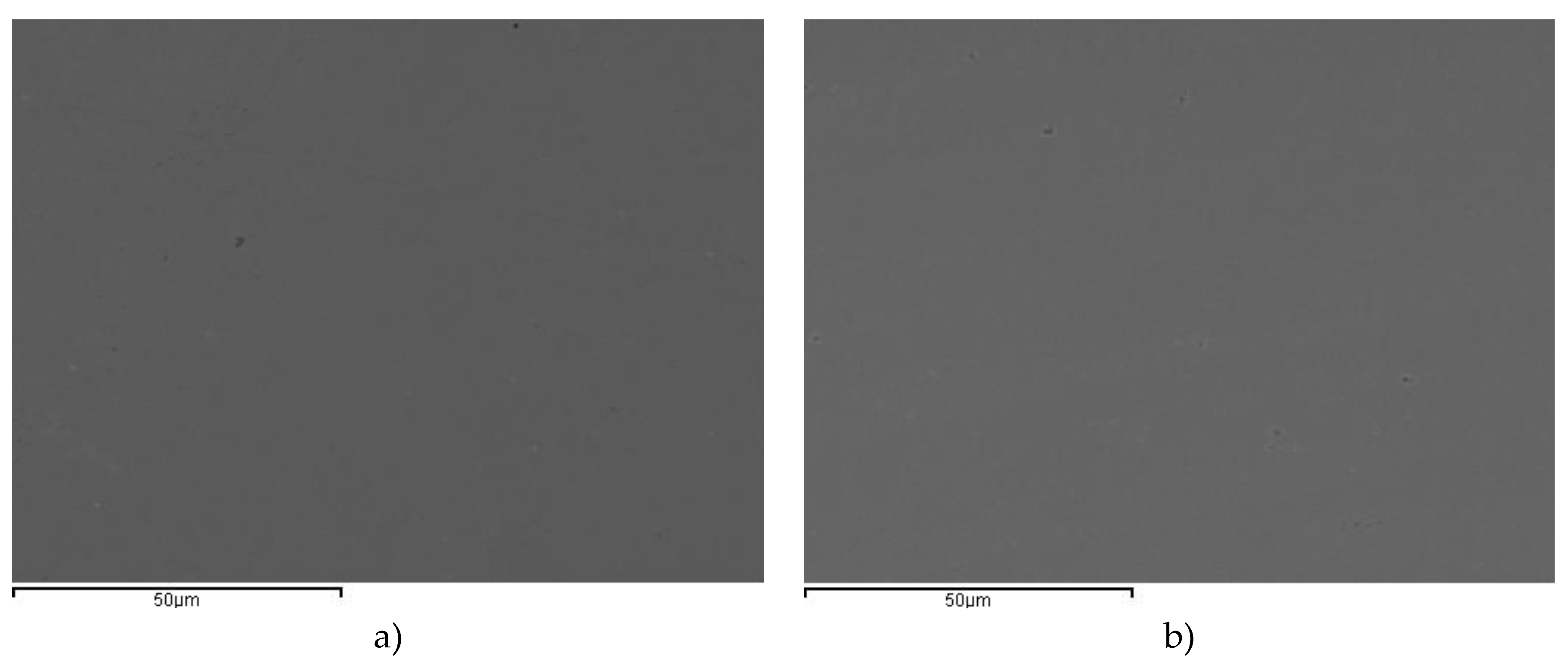
Figure 2.
Potentiodynamic polarization curves obtained in in 3.5% NaCl solution for AISI 304 and 436 with 1µm surface finish from -0.6V to Ep at 1 mV s−1.
Figure 2.
Potentiodynamic polarization curves obtained in in 3.5% NaCl solution for AISI 304 and 436 with 1µm surface finish from -0.6V to Ep at 1 mV s−1.
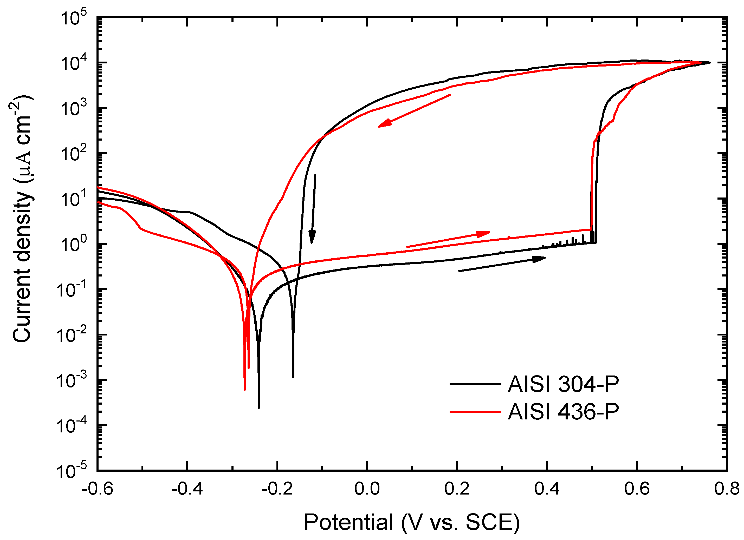
Figure 3.
SEM images for pitting corresponding to a) AISI 304-P and b) AISI 436-P after corrosion test.
Figure 3.
SEM images for pitting corresponding to a) AISI 304-P and b) AISI 436-P after corrosion test.
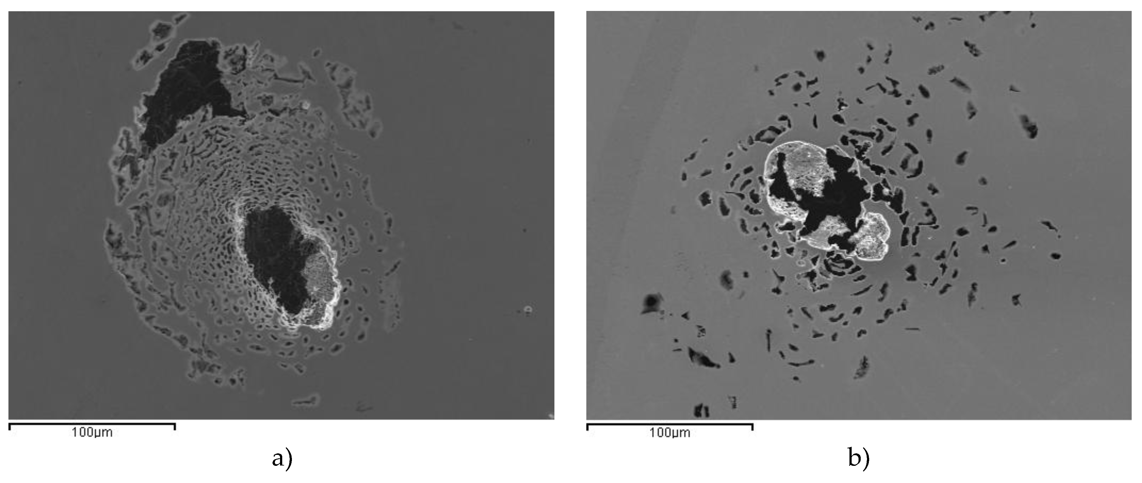
Figure 4.
SEM images corresponding to a) AISI 304-2B and b) AISI 436-2B before corrosion tests.
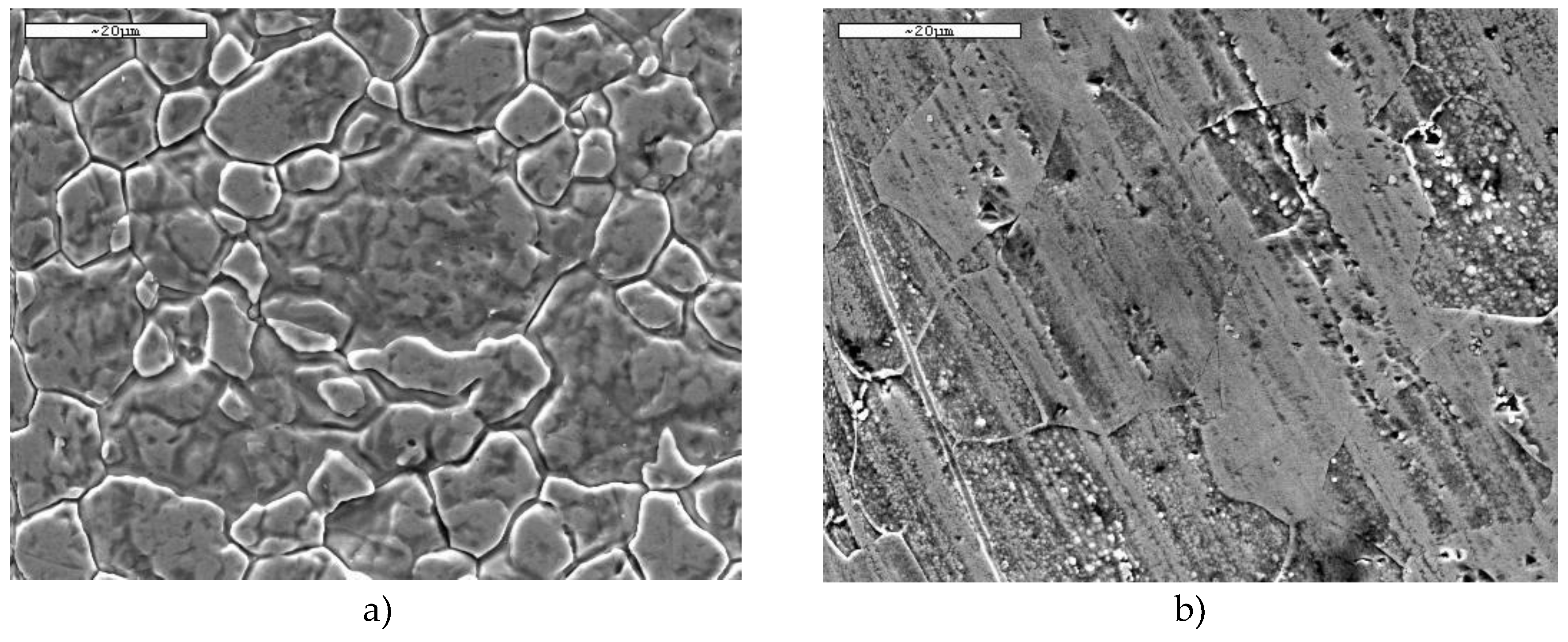
Figure 5.
Potentiodynamic curves obtained in 3.5% NaCl solution at 1mV s−1 for AISI 304 and 436 with ASTM 2B finish, from -0.6V to E corresponding to 104 A cm−2 for each material.
Figure 5.
Potentiodynamic curves obtained in 3.5% NaCl solution at 1mV s−1 for AISI 304 and 436 with ASTM 2B finish, from -0.6V to E corresponding to 104 A cm−2 for each material.
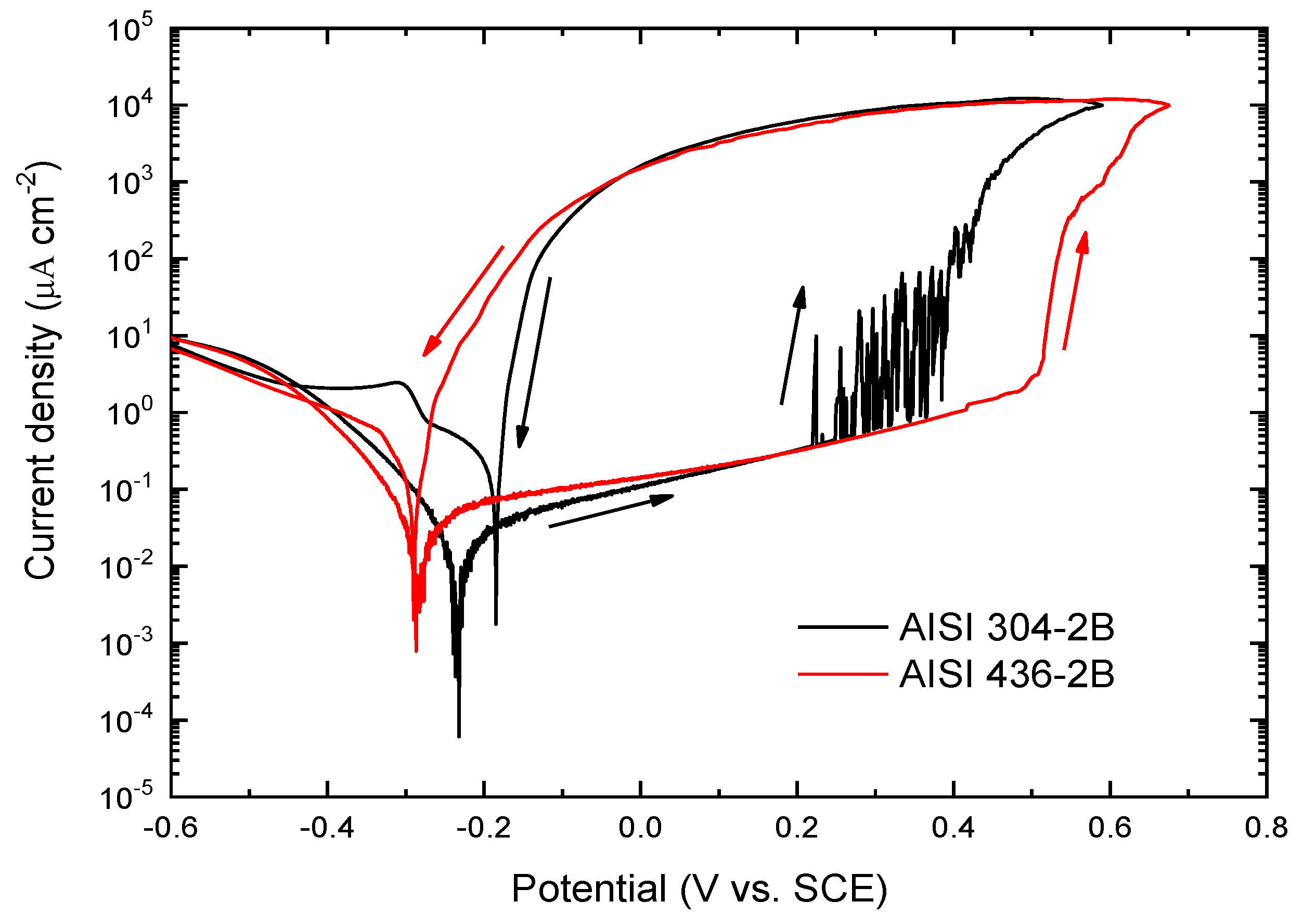
Figure 6.
SEM micrographs corresponding to the surface of AISI 304 steel with a 2B surface finish after the potentiodynamic curve.
Figure 6.
SEM micrographs corresponding to the surface of AISI 304 steel with a 2B surface finish after the potentiodynamic curve.
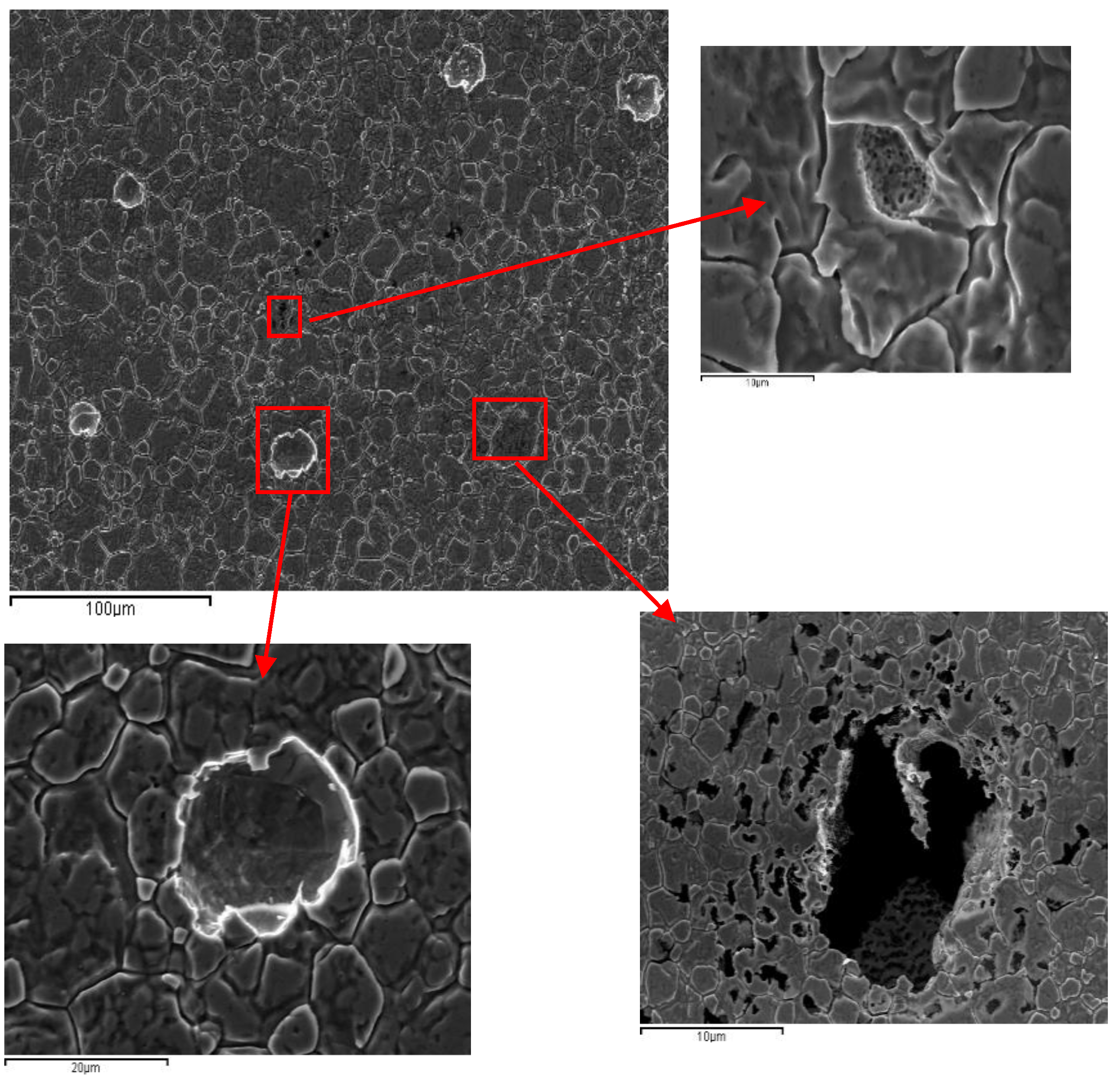
Figure 7.
SEM micrographs corresponding to the surface of AISI 436-2B steel after the potentiodynamic curve.
Figure 7.
SEM micrographs corresponding to the surface of AISI 436-2B steel after the potentiodynamic curve.
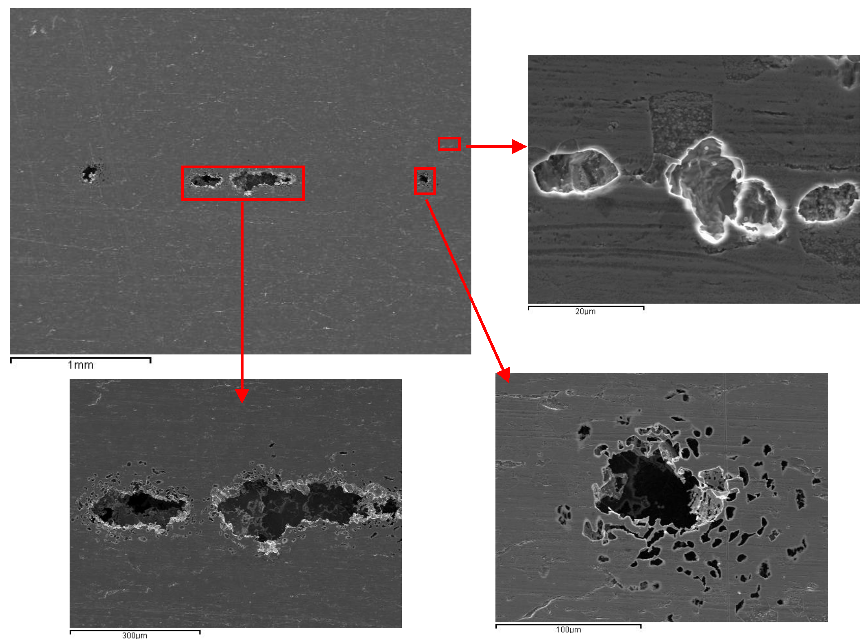
Figure 8.
SEM images corresponding to a) AISI 304-BA and b) AISI 436-BA before corrosion tests.
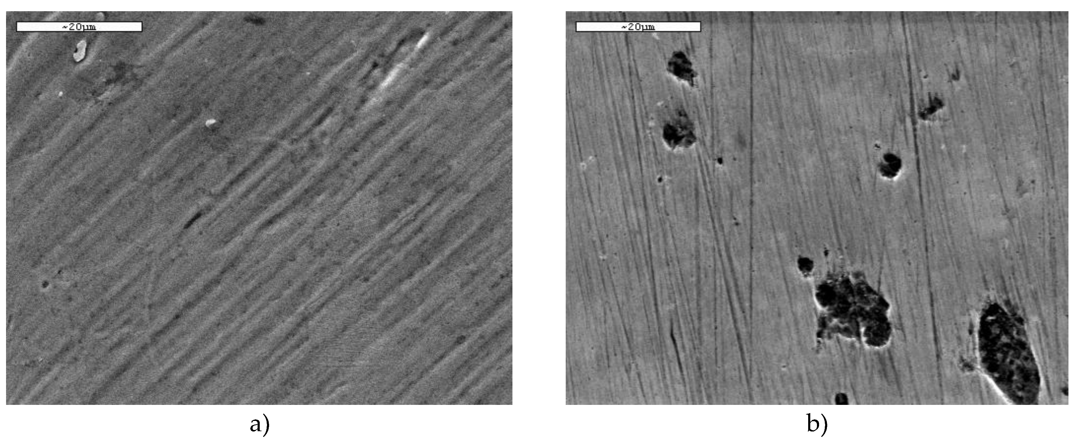
Figure 9.
EDS results corresponding to a dark area observed in AISI 436-BA.
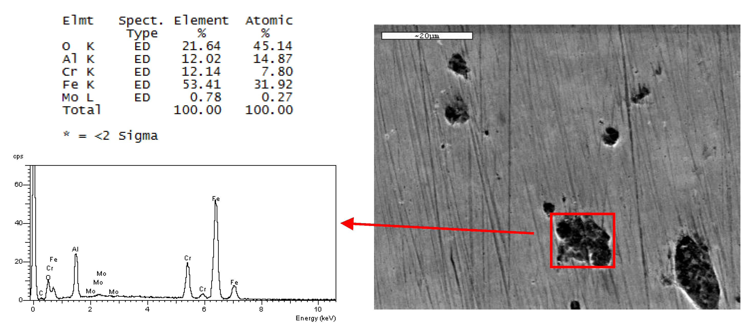
Figure 10.
Potentiodynamic curves obtained in 3.5% NaCl solution at 1 mV s−1 for the AISI 304 and 436 steels with ASTM BA finish, from -0.6V to Ep (i= 104 A cm−2).
Figure 10.
Potentiodynamic curves obtained in 3.5% NaCl solution at 1 mV s−1 for the AISI 304 and 436 steels with ASTM BA finish, from -0.6V to Ep (i= 104 A cm−2).
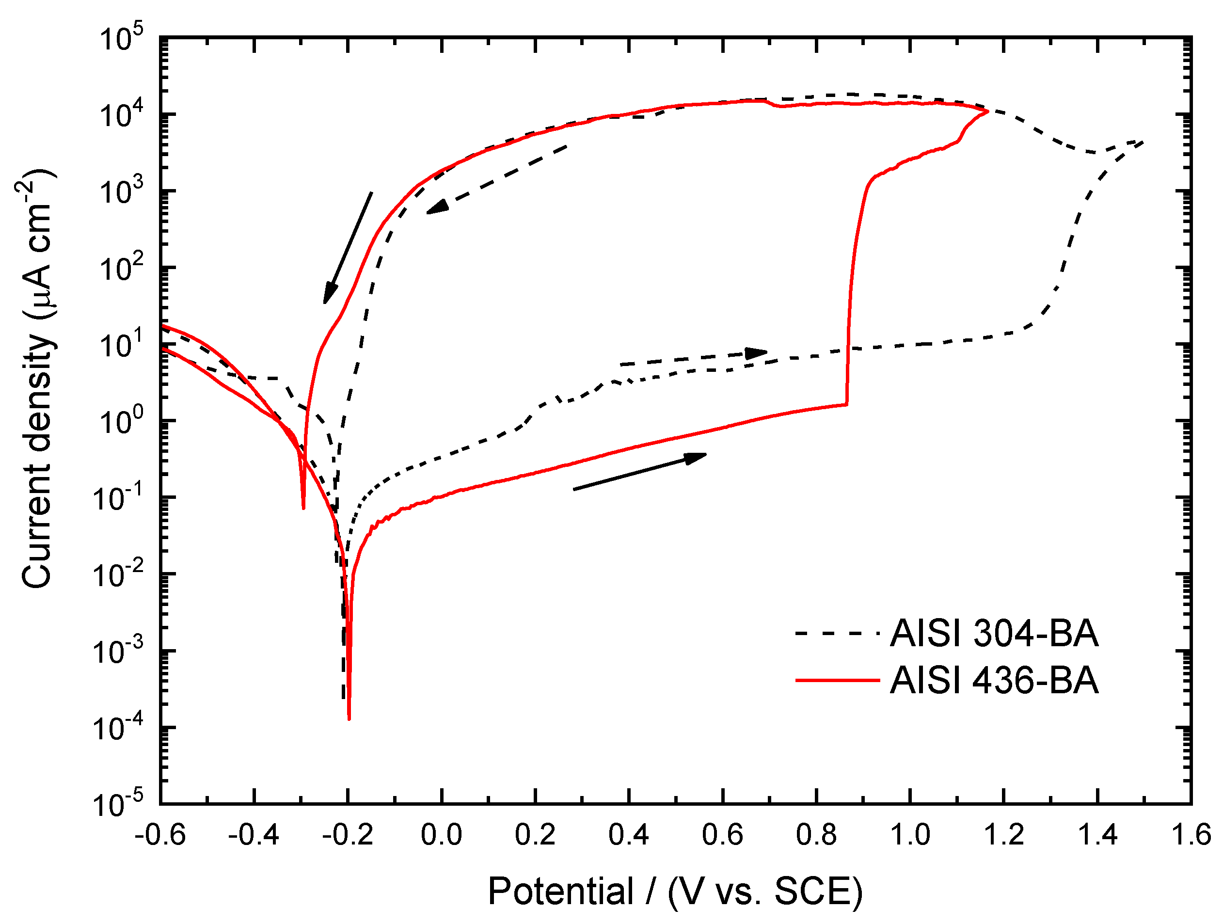
Figure 11.
SEM micrograph for AISI 304-BA and after potentiodynamic measurements.
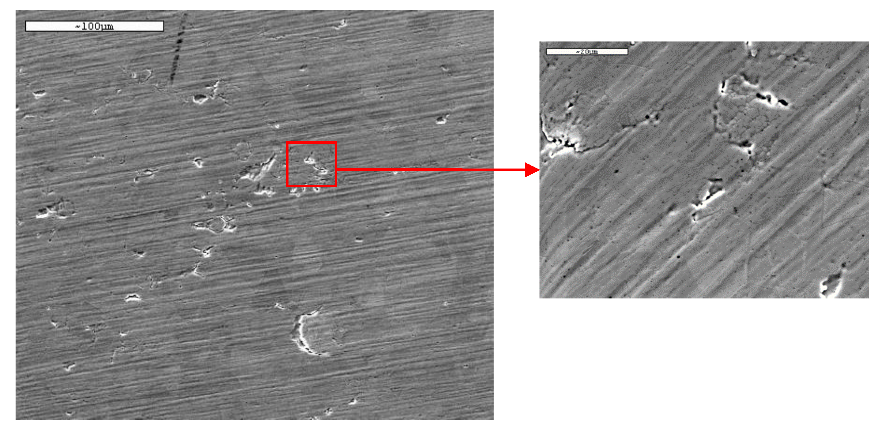
Figure 12.
SEM micrographs for AISI 436-BA after potentiodynamic measurements in 3.5% NaCl solution.
Figure 12.
SEM micrographs for AISI 436-BA after potentiodynamic measurements in 3.5% NaCl solution.
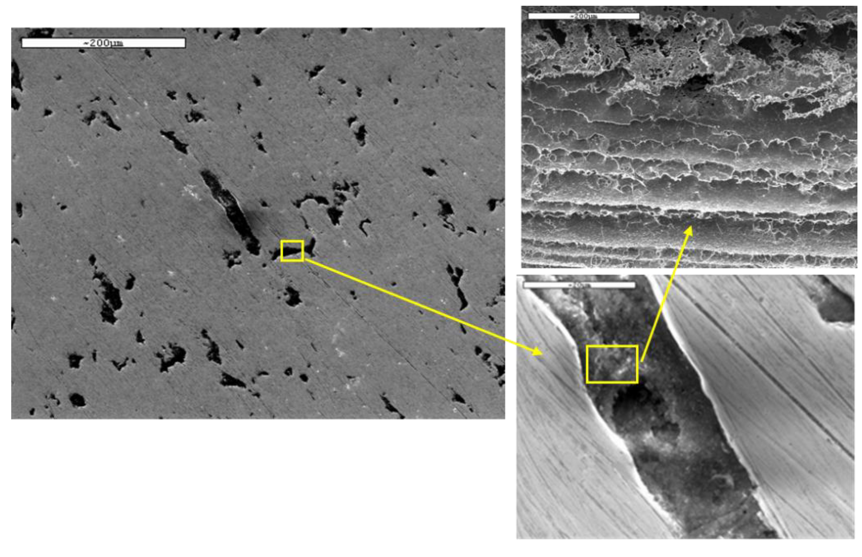
Figure 13.
Evolution of friction coefficient during the wear test of the AISI 304 steel with different surface conditions (P, 2B and BA).
Figure 13.
Evolution of friction coefficient during the wear test of the AISI 304 steel with different surface conditions (P, 2B and BA).
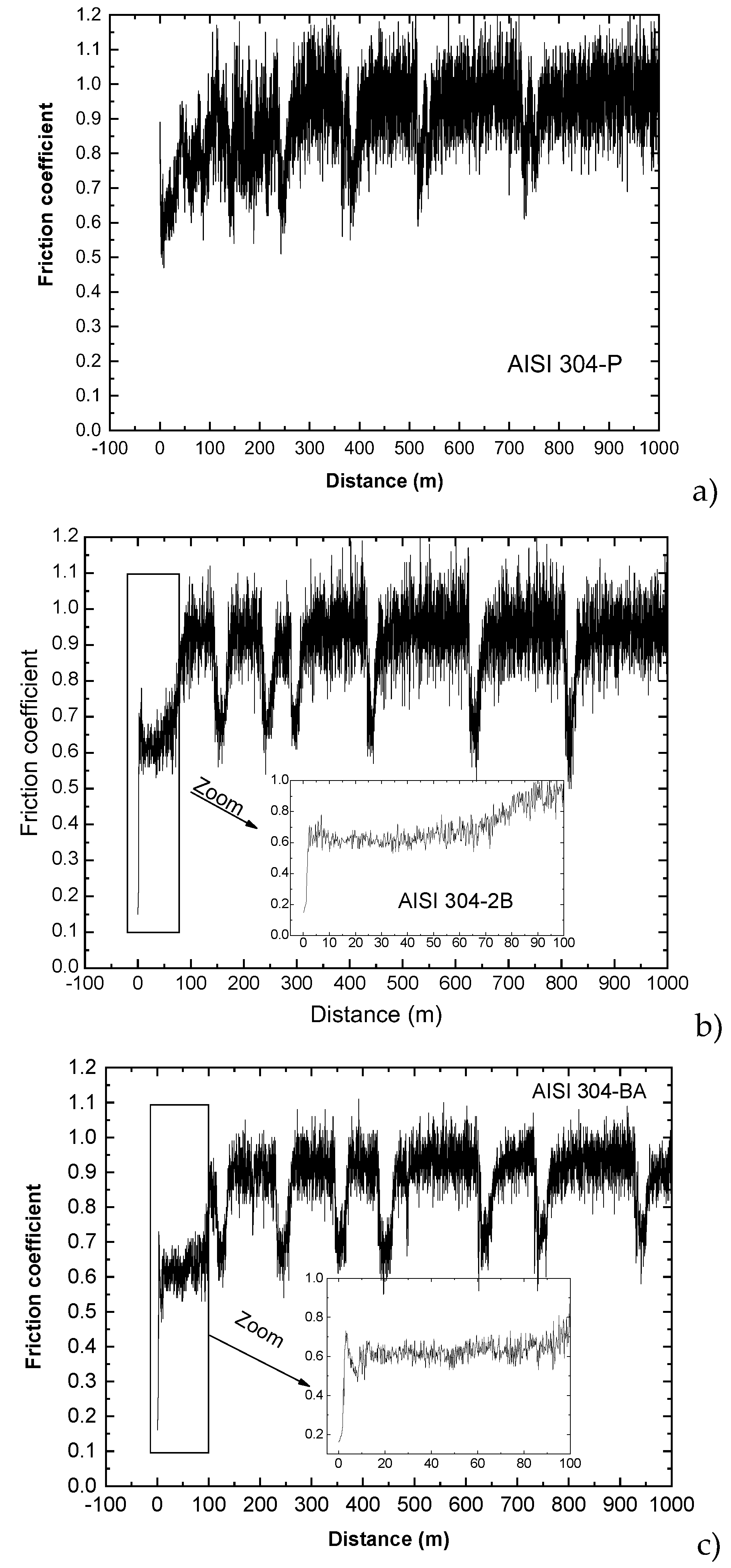
Figure 14.
SEM images corresponding to the wear test when the friction coefficient reaches the maximum value (a) and minimum value (b) for AISI 304-P steel.
Figure 14.
SEM images corresponding to the wear test when the friction coefficient reaches the maximum value (a) and minimum value (b) for AISI 304-P steel.
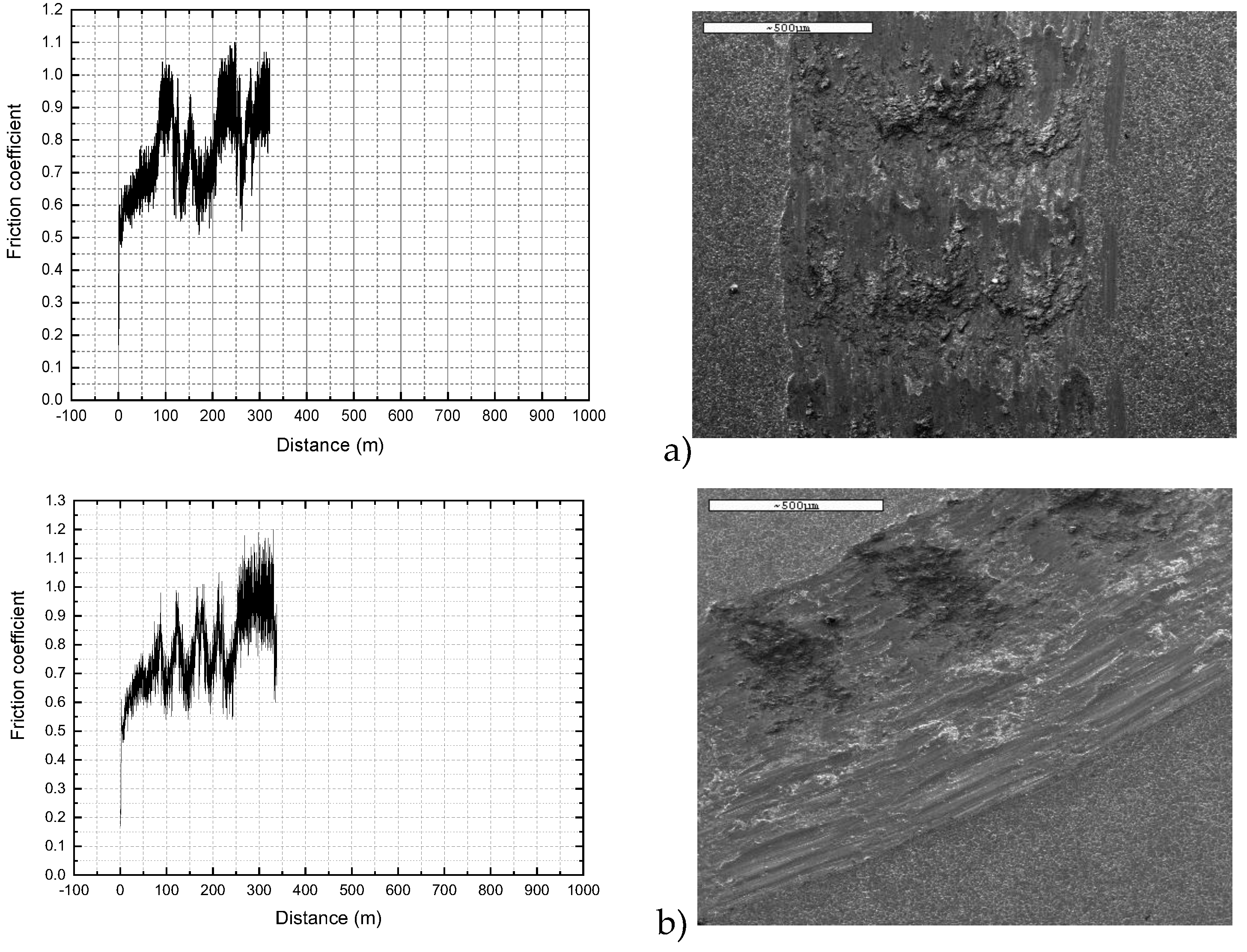
Figure 15.
Figure 15. Evolution of the coefficient of friction during the wear test of AISI 436 steel with different finishes a) P condition, B) 2b condition and c) BA condition.
Figure 15.
Figure 15. Evolution of the coefficient of friction during the wear test of AISI 436 steel with different finishes a) P condition, B) 2b condition and c) BA condition.
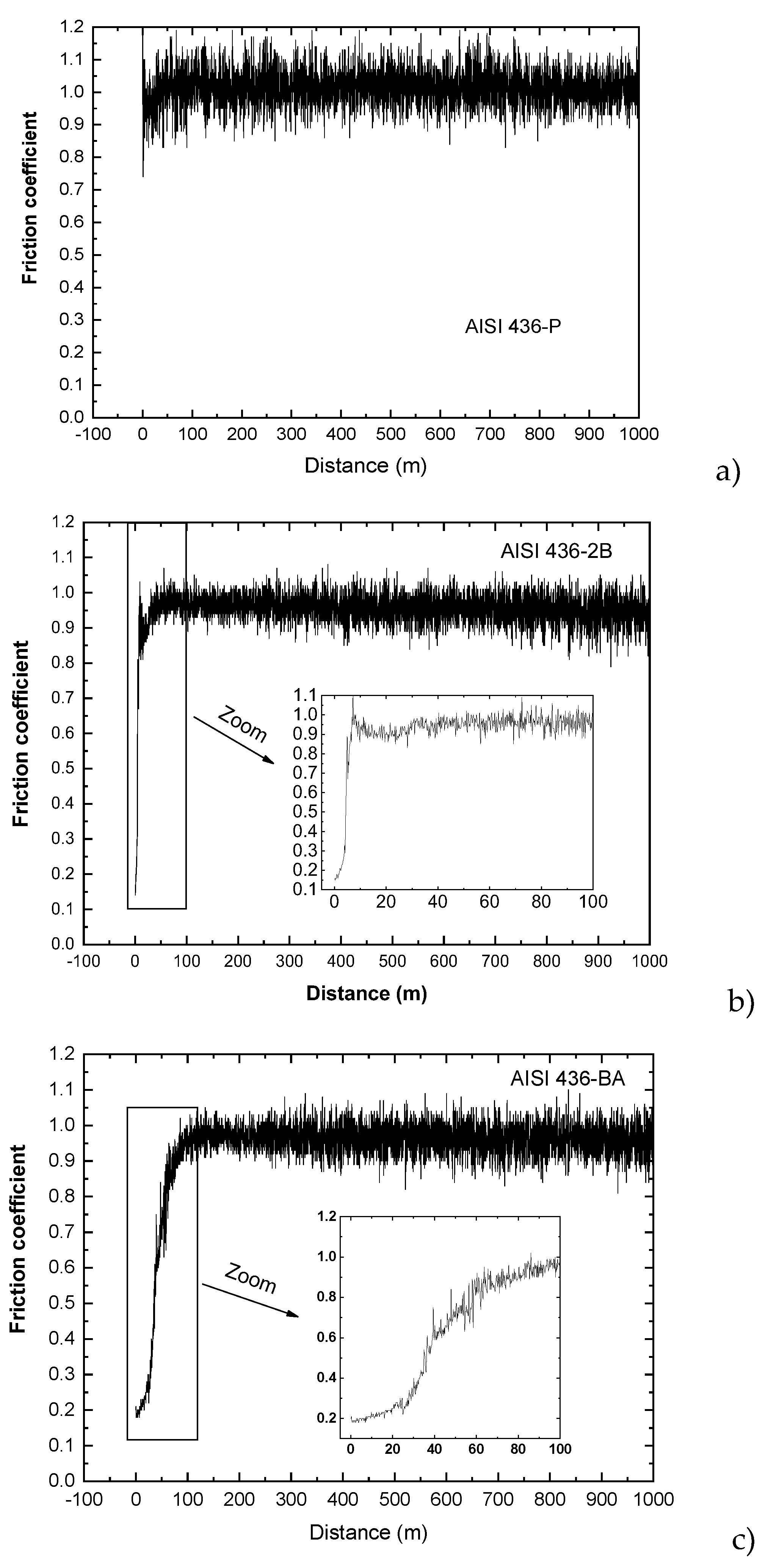
Figure 16.
Figure 16. SEM micrographs obtained for the AISI 436-P steel on the worn surface. The white arrow indicates sliding direction.
Figure 16.
Figure 16. SEM micrographs obtained for the AISI 436-P steel on the worn surface. The white arrow indicates sliding direction.
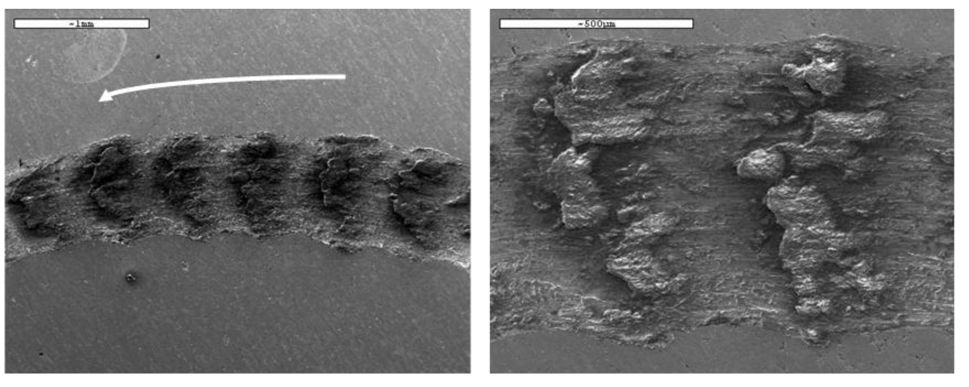

Table 1.
Chemical composition in wt.% of the Stainless Steels used in this study.
| Element | Fe | C | Cr | Ni | Si | Mn | Mo | |
| AISI 304 | Wt.% | Bal. | 0.05 | 18.20 | 8.05 | 0.05 | 1.10 | - |
| AISI 436 | 0.04 | 17.50 | - | 0.04 | 0.50 | 1.25 |
Disclaimer/Publisher’s Note: The statements, opinions and data contained in all publications are solely those of the individual author(s) and contributor(s) and not of MDPI and/or the editor(s). MDPI and/or the editor(s) disclaim responsibility for any injury to people or property resulting from any ideas, methods, instructions or products referred to in the content. |
© 2025 by the authors. Licensee MDPI, Basel, Switzerland. This article is an open access article distributed under the terms and conditions of the Creative Commons Attribution (CC BY) license (http://creativecommons.org/licenses/by/4.0/).
Copyright: This open access article is published under a Creative Commons CC BY 4.0 license, which permit the free download, distribution, and reuse, provided that the author and preprint are cited in any reuse.


